Operation
93
Model MMV Rev. 10/11
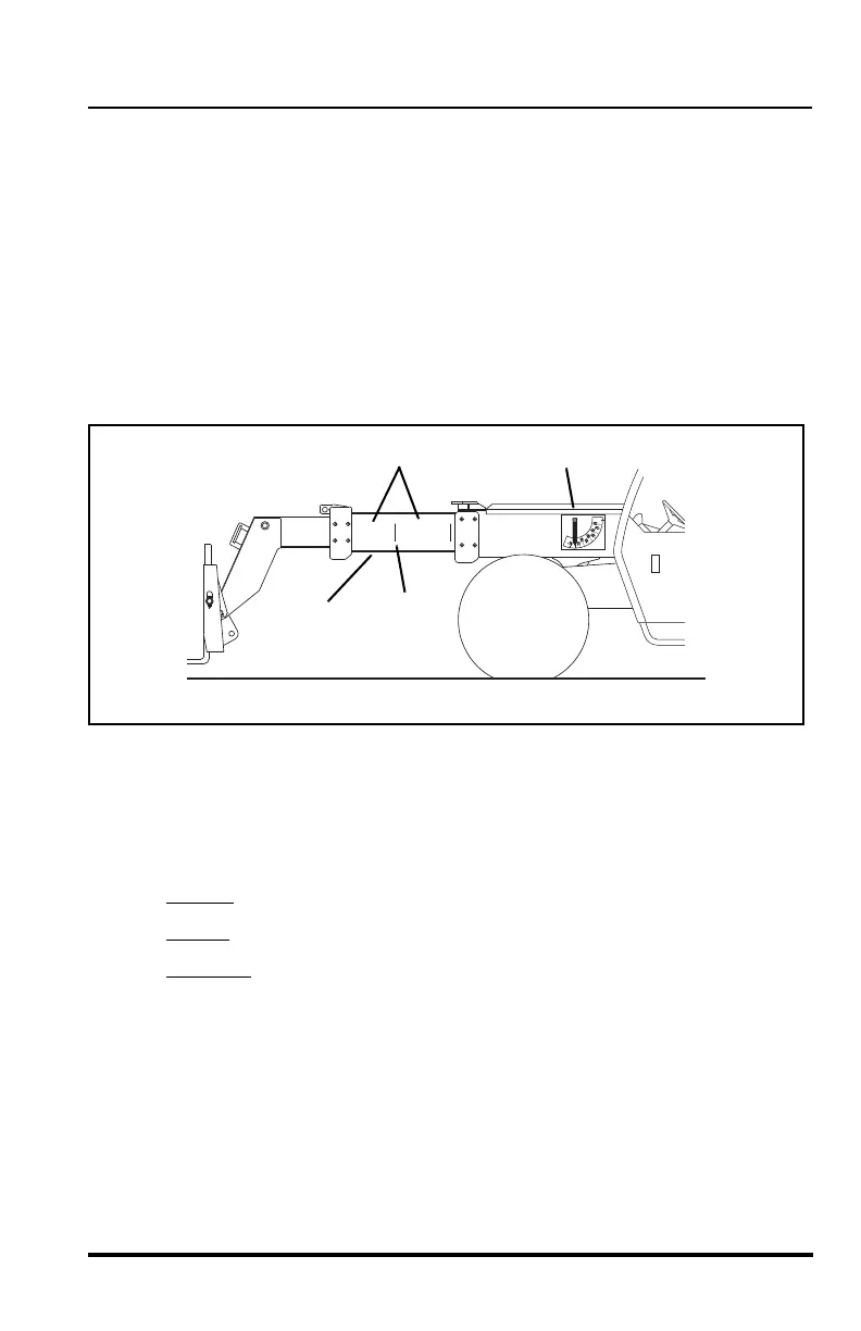
The vehicle is equipped with two indicators that will assist the operator in
determining how to accurately use the capacity chart. These indicators are:
• boom extend letters (1)
• boom angle indicator (2)
As the boom is extended, boom extend letters (1) and vertical dividing lines
(3) become visible on the left side of the intermediate boom (4). These
letters and vertical lines indicate the point (zone) of boom extension and
correspond to the capacity chart. For example, when the boom extend “B”
first appears, the boom is at the point of boom extension corresponding to
an arc of line “B” on the capacity chart.
The boom angle indicator (2), located on the left side of the outer boom,
indicates the angle of the boom and also corresponds with the angles
indicated on the capacity chart.
To accurately use the capacity chart, the operator must first determine three
important things:
1. Weight
of the load being lifted.
2. Height
of the structure where the load is to be placed.
3. Distance
where the load will ultimately be placed in front of the front
tires.
IMPORTANT! If operating the vehicle at 60 psi (414 kPa) or 45 psi
(310 kPa) reduced tire pressures, refer to “Load Capacity To Travel Speed
Tables” begining on page 94 for proper operating capacities and speeds.
ALWAYS refer to the proper load chart in the operators cab when working
with a load.