SEMI-AUTOMATIC
40
11 Compliance with electromagnetic emission standards
The following paragraphs specify compliance with the electromagnetic emission standards:
▪ Guidelines and manufacturer declaration - Electromagnetic emissions
▪ Guidelines and manufacturer declaration - Electromagnetic immunity
▪ Recommended distances between portable and mobile radiofrequency communication equipment and the
AED
11.1 Guidelines and manufacturer declaration - Electromagnetic
emissions
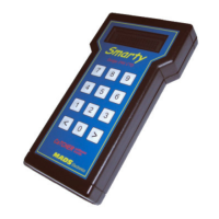
SMARTY Saver Plus was designed to be used in electromagnetic environments with the following characteristics.
Electromagnetic environment - Guidelines
The AED uses RF energy only for its internal operation. Its
RF emissions are, therefore, very low and it is improbable
that they may interfere with electronic devices nearby.
The AED can be used in any building, including residential
buildings and buildings directly connected to the public
low-voltage electricity network that supplies residential
buildings.
Harmonic Emissions
IEC 61000-3-2
Voltage
fluctuations/flickers
IEC 61000-3-3
11.2 Guidelines and manufacturer declaration - Electromagnetic
immunity
SMARTY Saver Plus was designed to be used in electromagnetic environments with the following characteristics.
Test level
IEC/EN 60601-1
Electromagnetic environment
Guidelines
Electrostatic discharge
(ESD)
IEC 61000-4-2
The floors must be made of wood,
cement or ceramic bricks. If the floors
are covered by synthetic materials, the
relative humidity must be at least 30%
Fast transients/burst
IEC 61000-4-4
±2 kV for electricity
networks
< 5% U
T
(> 95% dip in U
T
) for
0.5 cycles
40% U
T
(60% dip in U
T
) for 5
cycles
70% U
T
(30% dip in U
T
) for
25 cycles
< 5% U
T
(>95% dip in U
T
) for
5 seconds