- 18 -
No.EX##-OMY0004
Cross circuit detection
If all inputs are parameterized without cross circuit detection, a DC voltage can be sourced at the clock
outputs without clock pulses. As soon as cross –circuit detection has been parameterized for at least one
input pair, pulses are output at clock outputs UT1 and UT2.
For inputs that are parameterized with cross –circuit detection, the default assignment is as follows:
Inputs for channel 1 (IN0 - IN3) are assigned to clock output UT1.
Inputs for channel 2 (IN4 - IN7) are assigned to clock output UT2.
Other assignments are also possible.
Information on error detection according to clocking: see Section 3.3.5 “Clock outputs UT1 and UT2”.
3.3.7. Connection options for sensors depending on the parameterization
Sensors that meet various safety requirements depending on the parameterization can be connected to
the inputs.
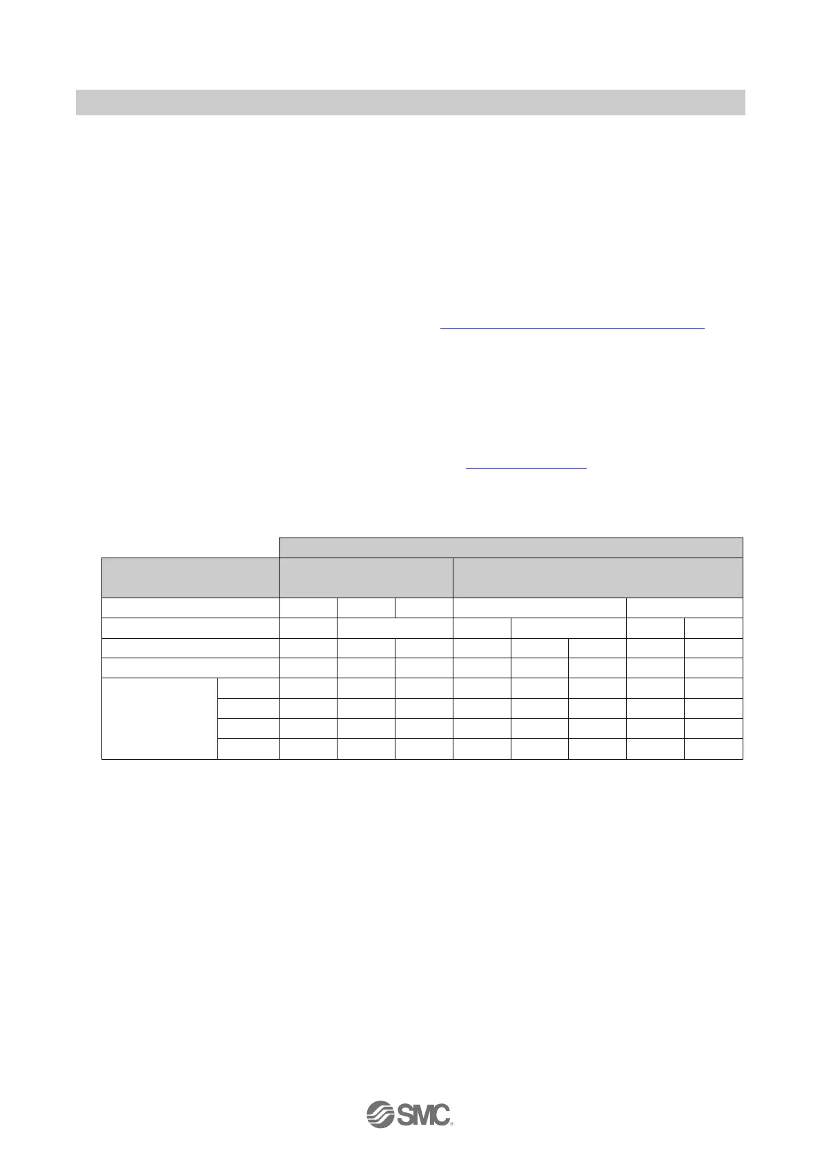
The maximum achievable SIL/SILCL/Cat./PL is specified in the table.
In order to meet the safety requirements:
Observe the information in the connection examples: see Section 7.2 “Wiring”.
Observe the requirements of the standards with regard to the external wiring and the sensors to be
used to achieve a SIL/SILCL/Cat./PL.
Table 3-1 Maximum achievable SIL/SILCL/Cat./PL
: Cat. 3 can only be achieved with a redundant sensor (2 series NO contacts) and a connecting cable that meets the fault exclusion
requirement of EN13849-2.
: The category that can be achieved depends on the sensor used.

 Loading...


