EasyManuals Logo
Home>SMC Networks>Control Unit>EX245-FPS1

SMC Networks EX245-FPS1 User Manual

SMC Networks EX245-FPS1
113 pages
To Next Page IconTo Next Page
To Previous Page IconTo Previous Page
Page #65 background imageLoading...
Page #65 background image
- 64 -
No.EX##-OMY0004
10.9.2.2. IN0-7 LEDs
Table 10-25 IN0-7 LEDs
IN0-7
Meaning
ON
Input is ON
OFF
Input is OFF
10.9.2.3. OUT M, OUT Z1-Z3 LEDs
Table 10-26 OUT M, OUT Z1-Z3 LEDs
OUT
Meaning
OFF
Safe output is OFF
Green ON
Safe output is ON
Red ON
Error detected.
(e.g. Short circuit, overload of the safe output, internal test error)
The safe output is switched OFF.
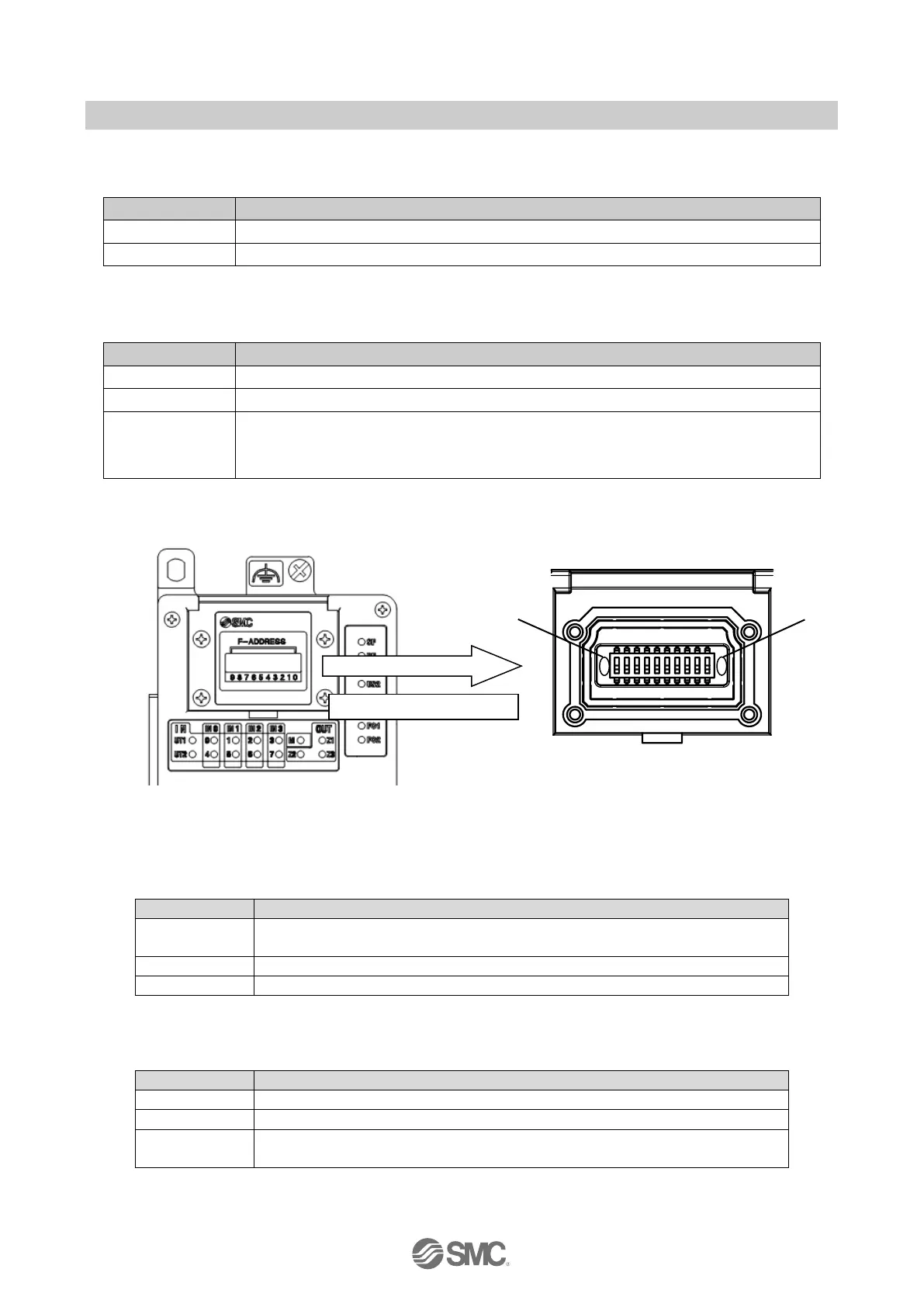
10.9.3. LED indicators 3
Fig. 10-5 LED indicators 3 of the EX245-FPS1/2/3
10.9.3.1. FS LED
Table 10-27 FS LED
LED state
Meaning
OFF
The safety application has valid F-Parameters and i-Parameters
(Only applies if US1 is on at the same time)
Red ON
Hardware fault. Communication to the higher level safe controller is disabled
Red Flash
Module is not parameterized or parameterization was not accepted
10.9.3.2. P LED
Table 10-28 P LED
LED state
Meaning
OFF
No safe communication
Green ON
Safe communication is running.
Green Flash
Safe communication is running.
The controller is requesting ‘operator acknowledgment’
Inside the switch cover
P LED
FS LED

Table of Contents

Questions and Answers:

Question and Answer IconNeed help?

Do you have a question about the SMC Networks EX245-FPS1 and is the answer not in the manual?

SMC Networks EX245-FPS1 Specifications

General IconGeneral
BrandSMC Networks
ModelEX245-FPS1
CategoryControl Unit
LanguageEnglish

Related product manuals