- 67 -
No.EX##-OMY0004
10.11.2.1. SW2
Not in use.
10.11.2.2. SW3
The two bits of the DIP-Switch “SW3” are used for the commissioning mode (COMNG_MODE).
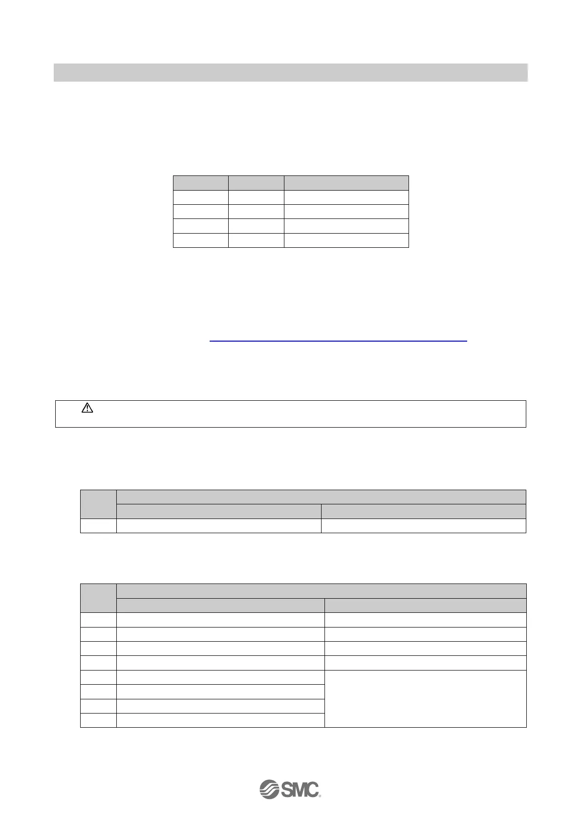
Table 10-29 SW3 details
●The setting of the DIP switch SW3 is read during power-up. It is not permitted to change the settings
during normal operation as this may cause an error.
●The hardware configuration must include the correct ‘Safe digital I/O’ module. If the DIP switch is set
for SM (Safety mode) then use the ‘Safe digital I/O (SM)’ module. Alternatively if the DIP switch is set
for CM (Commissioning mode) then use the ‘Safe digital I/O (CM)’ module. Both modules are resident
in the Step7 or PCWorx hardware catalogue after the device GSDML (Step7/TIA) or FDCML (PCWorx)
file has been imported into it. Refer to Section: 8.1.1“GSD file and symbol files” for details.
●“COMNG_MODE” occupies 1 byte for input data and 1 byte for output data.
●Diagnostics messages are supported.
●Parameters for safe-IOs are fixed in the firmware and are not adjustable
●F-Address should be in a parameter
Caution
In a production environment the SI unit must only be used in SM (Safety Mode)
IO mapping for the commissioning mode
IO Mapping for “COMNG_MODE”
Table 10-30 IO Mapping for “COMNG_MODE”
Input data from safe inputs
Output data for safe outputs
Byte 0 of “COMNG_MODE”
Table 10-31 Byte 0 of “COMNG_MODE” details
Input status of safe input 0
Safe power supply of US2 to the IO modules
Input status of safe input 1
Safe power supply of US2 to the valve zone 1
Input status of safe input 2
Safe power supply of US2 to the valve zone 2
Input status of safe input 3
Safe power supply of US2 to the valve zone 3
Input status of safe input 4
Reserved: Fixed 0
A non–zero value generates an error
Input status of safe input 5
Input status of safe input 6
Input status of safe input 7
 Loading...


