- 66 -
No.EX##-OMY0004
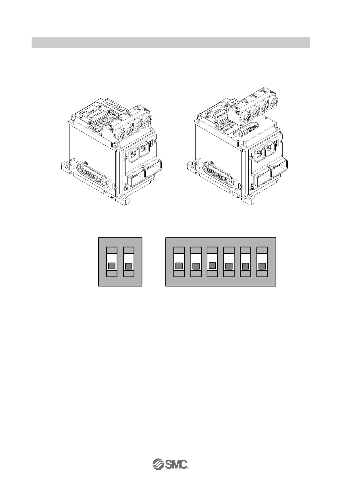
10.11.2. A two bit DIP-Switch and a six bit DIP-Switch
Two DIP-Switches SW2 and SW3 are under the M12 safe input connector box. To access the switches
remove the retaining screws as shown below.
Fig. 10-8 Retaining Screws
Fig. 10-9 SW3 and SW2 DIP switches
When the DIP-Switches have been set ensure the M12 connector block and all retaining screws are
refitted. (torque = 0.4 Nm)The module must be used in a fully assembled state with all parts securely
fastened before using the product
It is forbidden to make modifications to the module whilst setting the DIP-Switch values. Non-approved
modifications may compromise the module safety functionality and will invalidate the product guarantee

 Loading...


