- 87 -
No.EX##-OMY0004
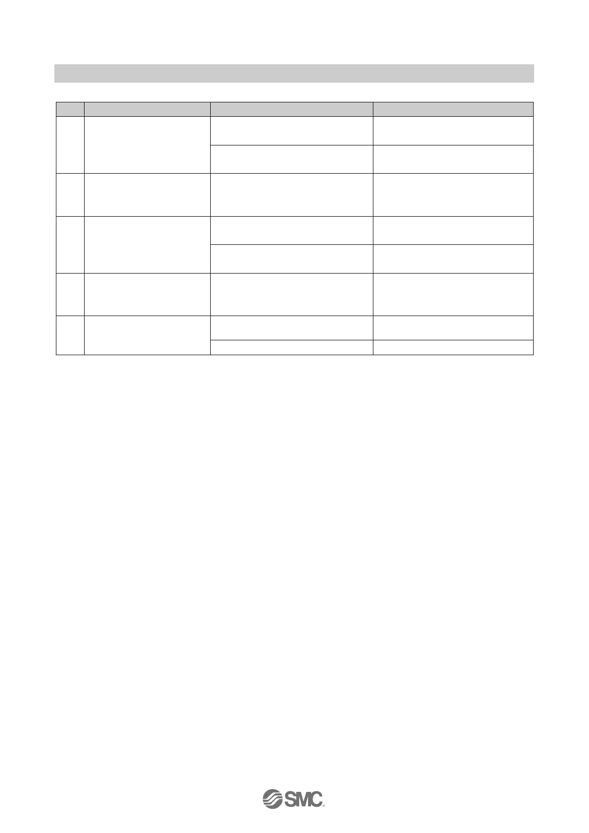
Table 16-3 Troubleshooting for Overall system
●Check the cable.
●Check the wiring and pin numbers.
US1 is not present or below the
dropout level (< approx. 17 VDC).
Check the supply for the logic/sensors.
US1 indicator is flashing.
US1 is below the permissible level
but above the dropout level (17 to
21.6 VDC).
Check the supply for the logic/sensors.
●Check the cable.
●Check the wiring and pin numbers.
US2 is not present or below the
dropout level (< approx. 17 VDC).
Check the supply for the valves/loads.
US2 indicator is flashing.
US2 is below the permissible level
but above the dropout level (17 to
22.8 VDC).
Check the supply for the valves/loads.
A solenoid valve is not
operating.
Check the connection with the SI
Unit.
Solenoid valve is faulty.
Check the solenoid valve.

 Loading...


