-19-
No.EX※※-OMZ0016
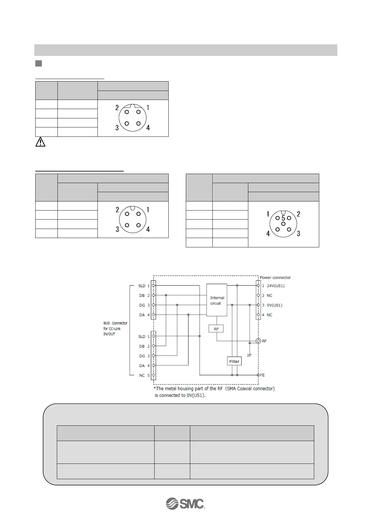
Connectors
•Power supply connector
No. Signal
1 24V (US1)
Caution
Note that connecting the power cable to BUS IN or BUS OUT will damage the product.
•BUS IN / BUS OUT connectors
No.
No.
Signal
M12, 4-pin, plug
Signal
M12, 5-pin , socket
The signal line of this product is T-branched inside the Base as shown in the circuit diagram below.
When expanding the system, an additional CC-Link remote device can be connected to BUS OUT.
•Circuit diagram
●Precautions for Handling
•Be sure to connect terminal resistors to both ends of the CC-Link main line.
Type of cable
Resistance
Terminating resistor model no. (Manufacturer)
Communication cable for CC-Link
PCA-1567720 (socket)
110Ω 1/2
W
•VA-4DCC-110 (Correns)
•CC100 (Woodhead Japan)
CC-Link dedicated high-
130 Ω 1/2
•VA-4DCC-130 (Correns)
 Loading...