HRX-OM-Q026
Chapter 3 Transport and Setting Up
HRSH Series 3.3 Installation
3-23
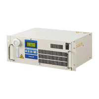
1. Prepare the flow switch described in the Table 3-9 (sold separately).
2. Depending on the external switch output type, connect the wire the switch to the
terminals for contact input signal as shown below. (This is an example of wiring. Refer
to the Operation Manual Communication Function for further details.)
Fig. 3-12 Wiring of the external switch (NPN open collector output) (example)
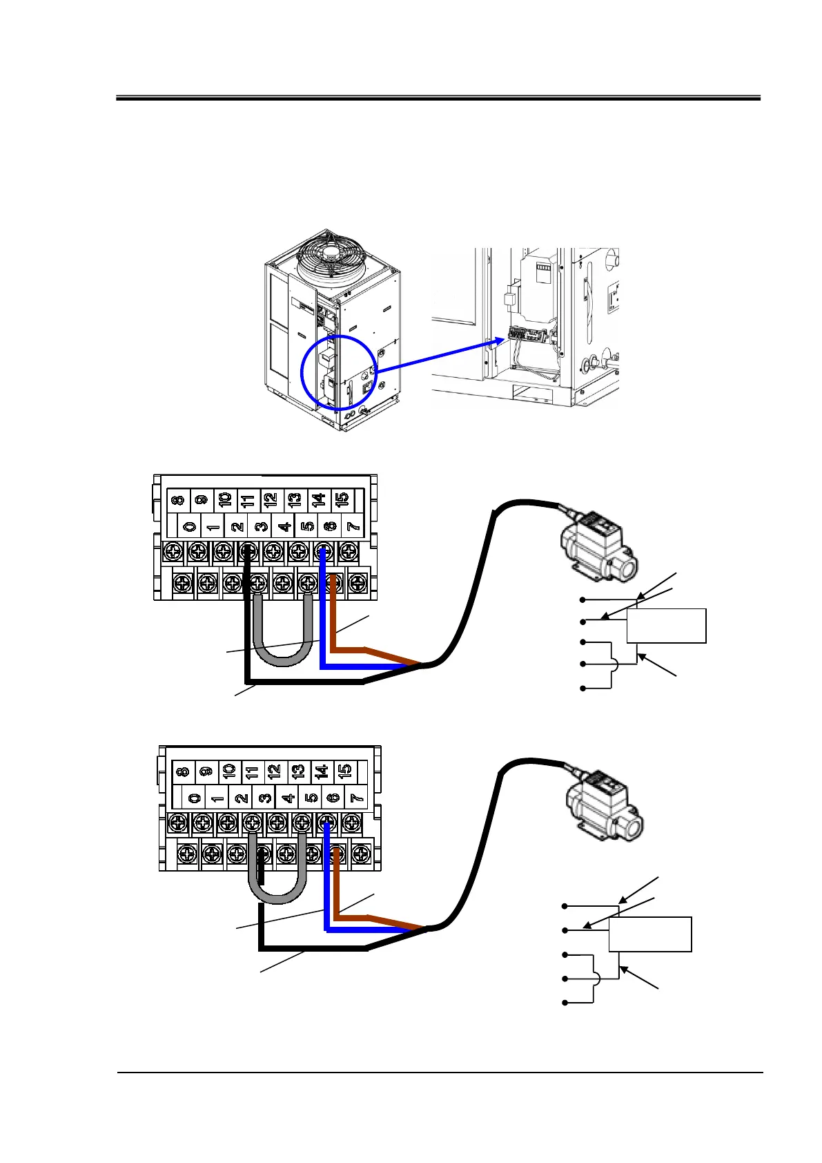
Fig. 3-13 Wiring of the external switch (PNP open collector output) (example)

 Loading...