1: 1/2 split range is available as split range setting (parameter code: 300).
2: <Ex.> When applying an input current of 80mA DC, an input power supply voltage of 12.5V DC or less can
prevent damage to the positioner.
Max. supply power = 80mA DC×12.5V = 1W
3: If the actuator rotating angle is 100
o
or less, its stroke can be adjusted optionally in a range from 0 to 60
o
and from 0 to 100
o
.
4: Linearity is a characteristic checked without loads using our
inspection machine. The positioner cannot work independently
and is used as a part of loop including actuating equipment
such as a valve, actuator and DCS. Therefore, it should be
noted that the described characteristic values may vary
depending on the loop conditions.
5: (ANR) shows standard air in accordance with JIS B0120.
6: The visibility of LCD display may be reduced at lower
temperature. This does not affect the positioner operation.
7: Voltage between terminals depends on temperature change.
8: Intrinsic safety type of explosion protected construction can be
selected from “How to Order”. If the explosion protected
construction specification is not selected, the product will not
have the explosion protected construction.
9: Connections can be selected from “How to Order".
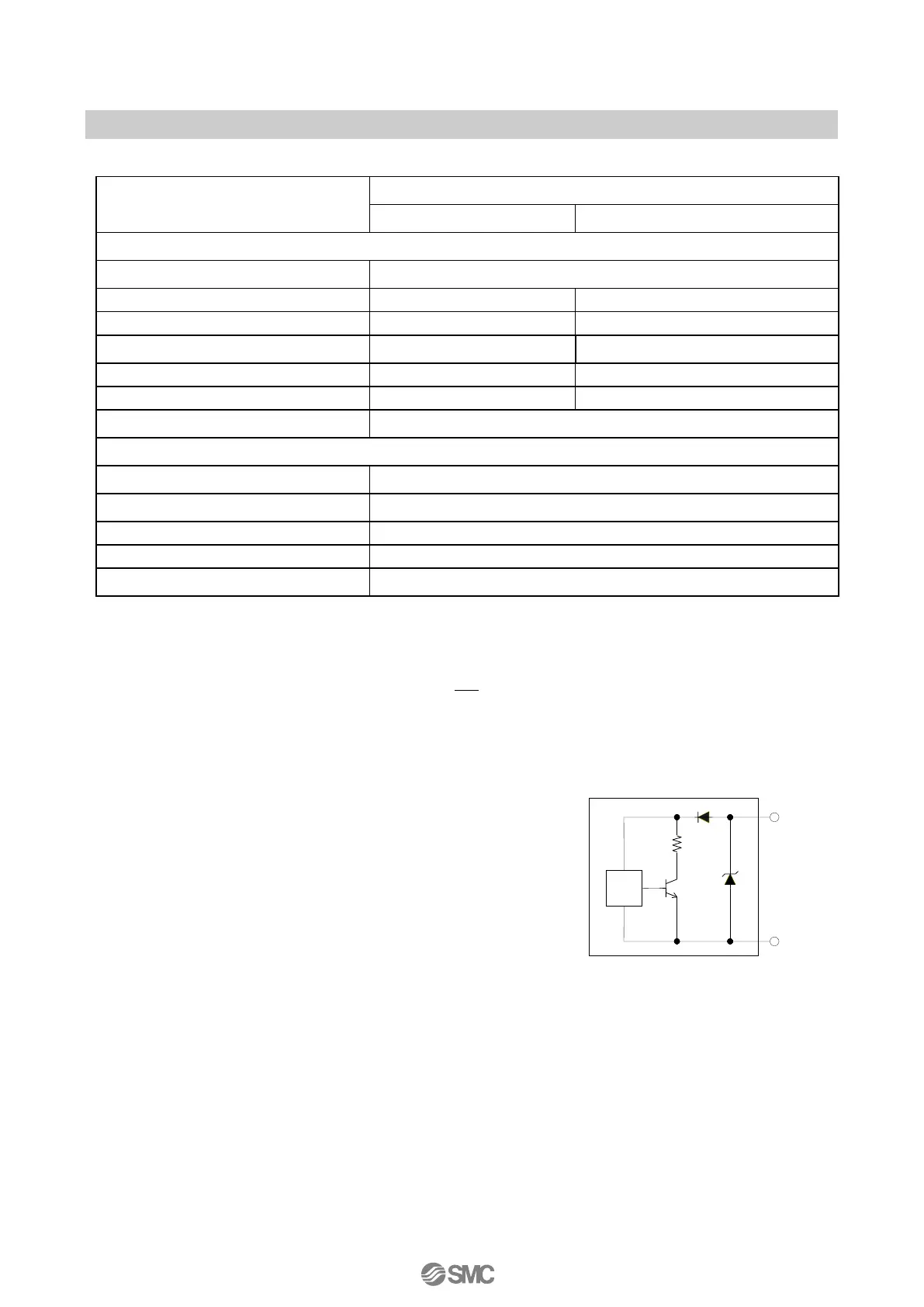
10: When no input current has been applied, an alarm is output.
Fig. 1 shows an internal alarm circuit of the IP8101-0*2-*
(Non explosion protected construction).
11: 10mADC or more load current is needed to operate the main circuit of the internal switch, and it should
be 40mADC or less to protect the internal resistance circuit. Therefore, use a power supply voltage and
load resistance with a load current of 10 to 40mADC when the output is on. (refer to ■Electrical wiring).
12: The current consumption to drive a main circuit of an internal switch is included.
13: Connect a load resistance with consideration given to the minimum power supply voltage (refer to
■Electrical wiring).
14: If input current is cut while analog output source voltage is supplied, analog output current before the cut is maintained.
15: Analog output accuracy to position value (P value) in the LCD display.

 Loading...