4.3MODESELECTION
Usethegaugearmtotouchtheinsiderimedge
position(B)forthetapeweightplacement.TheLED
willflashandtonewhenthevalueisstoredinm
emory.TheinnerLED(C)willflash.Continueto
extendthegaugearetothe(C)weightplacement
position.Whenthebalancertones, theposition is
accepted.Storethegaugearminthecomplete
homeposition.
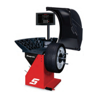
Themajorityofbalancingtakesplaceinthedefault
2‐plane dynamic mode. Green LED’s A and E (See
figure15)Hammer‐onclipweightswillbeplacedon
bothinsideandoutsideoftherimedge.Ifrequired,
select an optional weight placement mode by
pressing the Mode button until the appropriate
placementmodeisdisplayed.
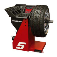
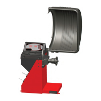
4.3.1WEIGHTPLACEMENTMODES
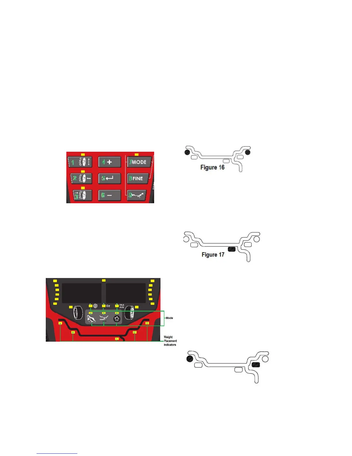
DYNAMIC(twoplanes)‐Suggestedfor allsteel
rims.Inthiscasethewheelweightsmustbe
clippedontotherimedges.Thisfunctionis
selectedasadefaultandtheLEDscorrespondin
gtothewheelweightlocationareliton(Figure
16).
Beforespinning thewheel(althoughitmaybedone
afterwards)choosetheappropriatebalancingmode
for the wheel. To select the various placement
modespress the (9) Weight Placement buttonuntil
placement LEDs indicate desired place ment
position.
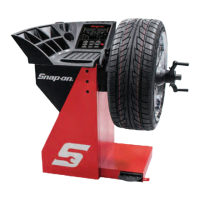
STATIC(singleplane)‐Suggestedfornarrowrims
(3"orless)oronlighttrucktireswithhigh
aspectratiotires.Useasinglecorrectiveweight
placedinthecenterofrimasillustratedin
Figure17.
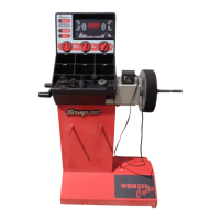
Figure14
1.TAPEWEIGHTMODEUSINGEASYWEIGHT
Tousethegaugearmtoindicatetheouterandinner
tape weight position. Press the Weight placement
number9keyuntilYellowLED’sBandClight.Press
the number 9 key one more time and LED 6 will
flash.
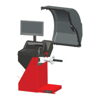
Figure15
WEIGHTCOMBINATIONMODESUSING
THEWEIGHTSELECTIONBUTTON
See(Figure14).Pressingtheweightselec
tionbutton(9)willtoggletheLED’stothe
weightdefaultselectionsasshown.Balancing
using acombinationofhammer‐onand
adhesiveweightsasshown.