Lit. No. 30118, Rev. 00 June 15, 2020
41
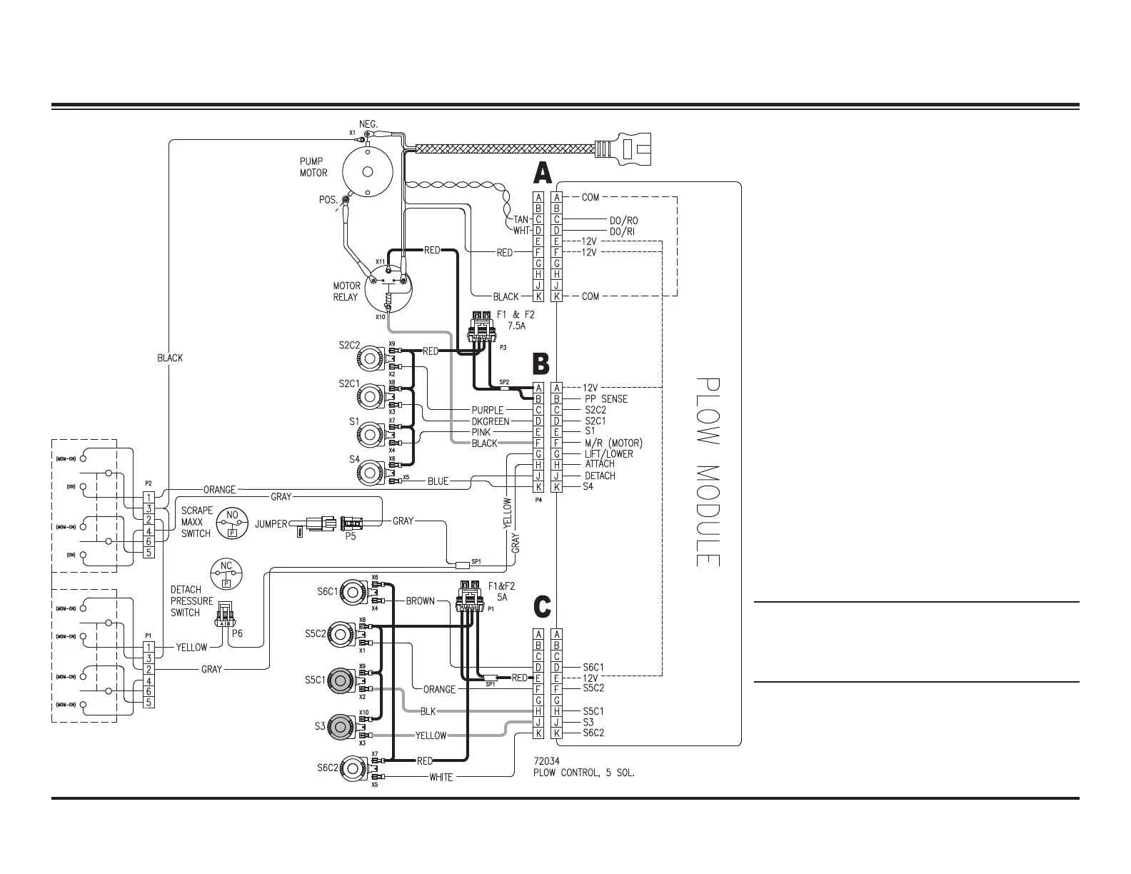
ANGLE LEFT – ELECTRICAL
System Response
1. Verify that the POWER switch is in the plow
position.
2. By activating the Angle Right function on the
cab control, the control sends a signal to the
plow module to complete the ground path for
the electrical circuit, activating the motor relay
and solenoid cartridge valves S5C1 and S3.
3. Hydraulic fl uid from the pump fl ows through the
activated S5C1 and S3 cartridge valves and
into the rod end of the left (driver-side) ram,
causing the ram to retract.
4. The retracting left ram pushes hydraulic fl uid
out of the base end of the ram, through the
activated PC1 pilot-operated check valve, back
through the activated S3 and through the PC2
valve. The fl uid then enters the base end of the
right (passenger-side) ram, causing the ram to
extend.
5. The extending left ram pushes hydraulic fl uid
out of the rod end of the ram and back through
the activated S5C1 to the reservoir.
NOTE: Battery voltage is supplied to the
plow module, motor relay and the 9 solenoid
coils when the snowplow is connected to the
vehicle.