This document can not be reproduced or released without the Sodikart authorization.
MAN.SIG.EN.02
04/2014
23
USE SPARE PARTS OF SODI ORIGIN
User maintenance guide
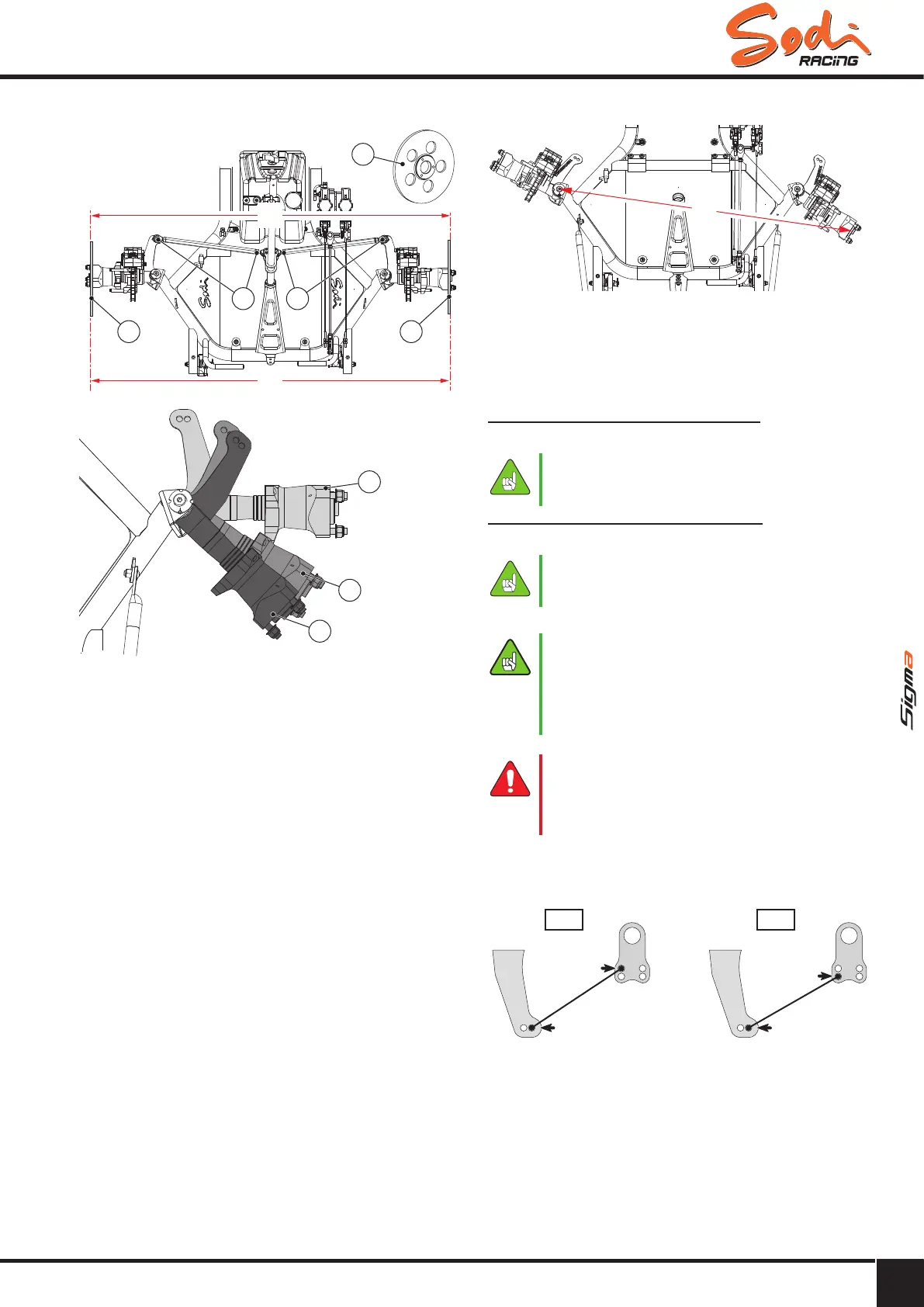
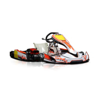
5.2.5 - Front wheel alignment
A
A = B
B
1
2 2
11
3
5
4
Legend
1 Wheel alignment disk
2 Tie rod nut and lock nut
3 Steering wheel in straight position
4 Maximum steering angle position
5 Steering wheel fully turned position
● Place the kart on a trolley.
● Place the front wheel alignment disk (1)
(available on ITAKA website).
● Unscrew the lock nuts (2) of the 2 tie rods.
Warning: lock nut of tie rod side is a right hand
thread; lock nut of steering column side is left-hand
thread.
● Position the upper branch of the steering wheel in
the kart axle.
● Measure A and B with a roll meter. Adjust the tie
rods until you get A=B with a tie rod length on the
right side 1.5mm bigger than the tie rod length on
the left side.
C
● Turn the steering wheel to put stub axle in position
(4), measure the dimension C.
● Turn the wheels in the opposite direction and
measure the dimension C for the second wheel.
● The two dimensions C must be equal.
Recommended setting on a dry track
● 2 mm opening : B = A +2mm.
●● Make●sure●the●dimensions●C●are●equal●on●
each●side.
Recommended setting on a wet track
● 7 mm opening : B = A +7mm.
●● Make●sure●the●dimensions●C●are●equal●on●
each●side.
● Remove the front wheel alignment disk (1).
●● Do●not●forget●to●tighten●the●2●lock●nuts●on●
the●tie●rods;●otherwise●the●parallelism●will●
be●lost●in●a●few●minutes.
●● Any●time●you●work●on●the●front●wheels,●
check●the●parallelism.●Do●the●same●after●
shocks.
► Never drive with badly tightened wheels:
it may lead to severe, even fatal injuries.
► Make sure that each ball joint penetrates
at least 5 threads in the tie rods.
5.2.6 - Adjustment of tie rods
1
B
B-1
2 1
A
B
1
A
2 1
A
B
A-1
● Standard adjustment: B-1
● Recommended in wet conditions: A-1.