38
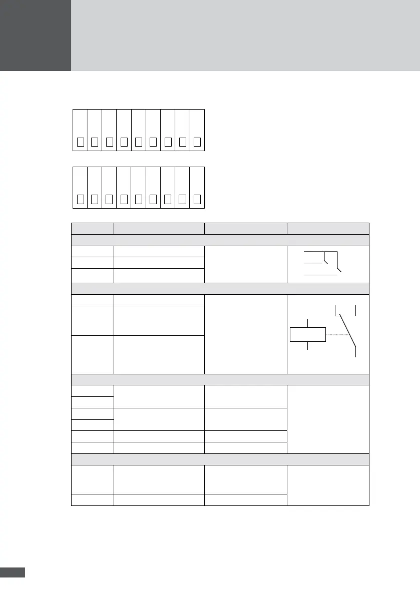
8�5 Terminal assignment
v+
GND
GND
AD0
AD1
IA
C
NC
NO
v+
GND
K6
K5
K4
K3
K2
K1
IB
Terminal Function Signal/Limit values Connection schema
External alarm inputs
GND GND for A und B for each input
– open: 15 V
– closed: < 10 mA
GND
IA
IB
IA Alarm input A
IB Alarm input B
Status signalling contact
C Reference maximum switching
capacity:
– AC: 230 V / 1 A
– DC: 30 V / 1 A
NO
C
NC
NC Closes to C in the event of
an inverter fault (no mains
supply).
NO Closed to C during normal
operation or in the absence
of communication with the
inverter (inactive state).
Irradiance and temperature sensors
GND
GND for V+
- -
GND
V+ Supply voltage for sensors
at AD0, AD1
15 Vdc / max. 0.5 A
V+
AD0 Irradiance 4…20 mA
AD1 Temperature 4…20 mA
MaxRemote
V+ Power supply for the relays
of the radio ripple control
receiver
15 VDC / max. 0.5 A see installation manual
“MaxRemote”
K1-K6 Digital inputs 15 VDC