This funciton can be achieved manually or automatically according to user’s wishes.
If user wants to use the off grid function manually, it need to be installed an external
switch. Please refer to specic wiring diagram below or as described in quick
installation guide.
And for automatical solution, please contact SolaX.
31
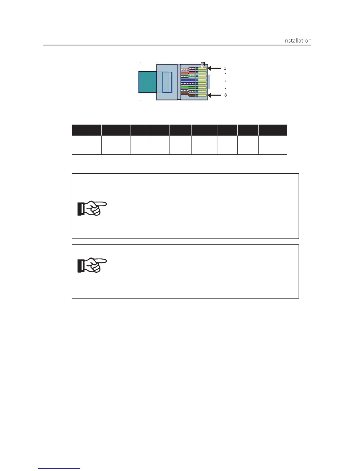
When connectingthe RJ45 connector with the wire of the CT or Meter , please
follow the below sequence :
Pin
1
CT
Red wire
2 3 4 5
X
76
X
8
X X X X
Green wire
Meter
Blue wire
White wire
X X X X XX
• Do not place the sensor on the N Wire or the earth wire.
• Do not place the sensor on the N and L wire simultaneously.
• Do not place the sensor on the L wire going to the consumer.
• Do not place the sensor with the arrow pointing to the generation
meter.
• Do not place the sensor on the non-insulated wires.
• Do not use the wire over 25m.
NOTE!
● EPS connection
The X-hybrid E version inverter has on and off grid function, the inverter will have
output through the grid output when the grid is on, and will have output through
the EPS output when the grid is off.
• The sensor can be upgraded to meter.
• With a one phase meter provided by SolaX can monitoring
the 24hr usage of electric.
• With a three phase meter provided by SolaX can implement
three phase compensation.
NOTE!
 Loading...
