30
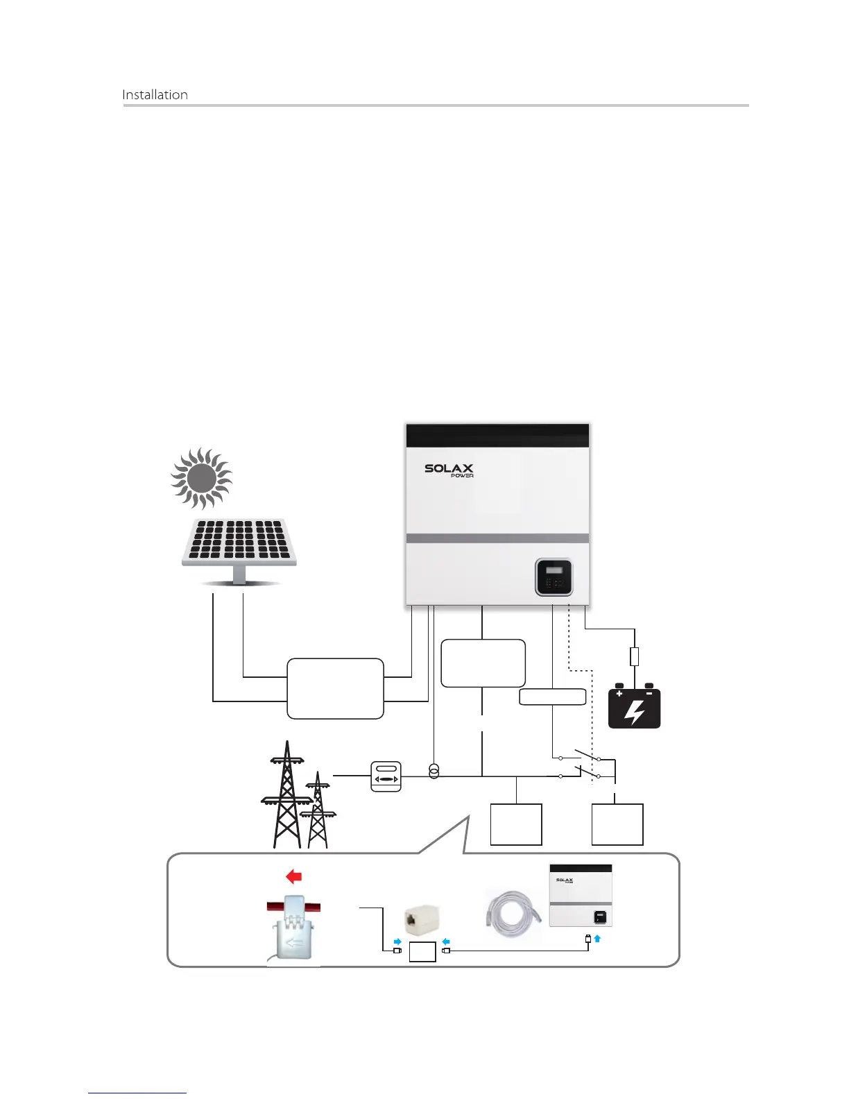
The current sensor measures the current on the phase wire that runs between
the inverter and the grid. This enables the inverter to determine the Power
requirements of the connected consumer. The current sensor is connected
to the CT port on the inverter.
Connection Step:
1. Insert the RJ45 terminal on the current sensor into the CT port on the inverter.
2. Place the current sensor around the phase wire L which the inverter is
connected.
3. Place the current sensor around the phase wire L to measure the current
going to or coming from the grid.
4. Make sure the current sensor is installed in the right direction: The arrow
on the current sensor must point to the public grid.
Ÿ Current sensor connection
X-hybrid inverter(E version)
Load
Current
sensor﹡
Electrical
grid
PV array
AC distribution box
*Fuse
*Battery
Surge arrestor
Fuse
AC Breaker
DC distribution box
Surge arrestor
Fuse
DC Breaker
Electric meter,
bidirectional
Grid EPS
EPS contactor
EPS
Load
L line
CT
Public
Grid
Breaker

 Loading...
