EasyManuals Logo

SolaX Power X1-EVC Series User Manual

SolaX Power X1-EVC Series
88 pages
To Next Page IconTo Next Page
To Previous Page IconTo Previous Page
Page #17 background imageLoading...
Page #17 background image
9
Product Overview
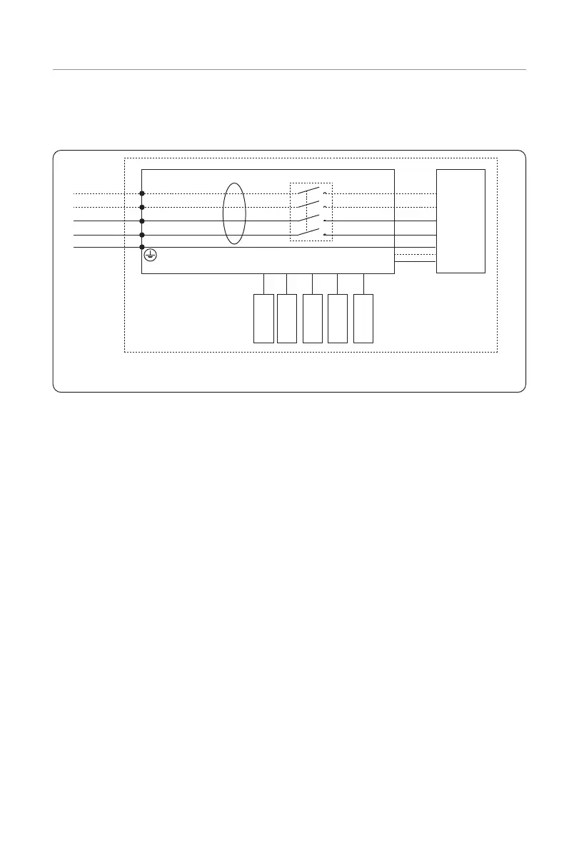
2.4 Principle Circuit Diagram
The principle design of the EV-Charger is shown in the figure below:
N
L1
L2
L3
PE PE PE
CP
PP
LED
CT
RFID
RS485
ESP32
INPUT-N OUTPUT-N
INPUT-L1 OUTPUT-L1
INPUT-L3
OUTPUT-L3
Central Control Board
Charging
Plug/Socket
Type A 30 mA + DC 6 mA
INPUT-L2 OUTPUT-L2
* L2, L3 are for three-phase EV-Charger.
PP is only for Socket Type.
The diagram for models named with "-P" is slightly different.
Figure 2-8 Principle Circuit Diagram

Table of Contents

Other manuals for SolaX Power X1-EVC Series

Questions and Answers:

Question and Answer IconNeed help?

Do you have a question about the SolaX Power X1-EVC Series and is the answer not in the manual?

SolaX Power X1-EVC Series Specifications

General IconGeneral
BrandSolaX Power
ModelX1-EVC Series
CategoryBattery Charger
LanguageEnglish

Related product manuals