"C/T" WIRING DIAGRAMS
Page 16 of 67
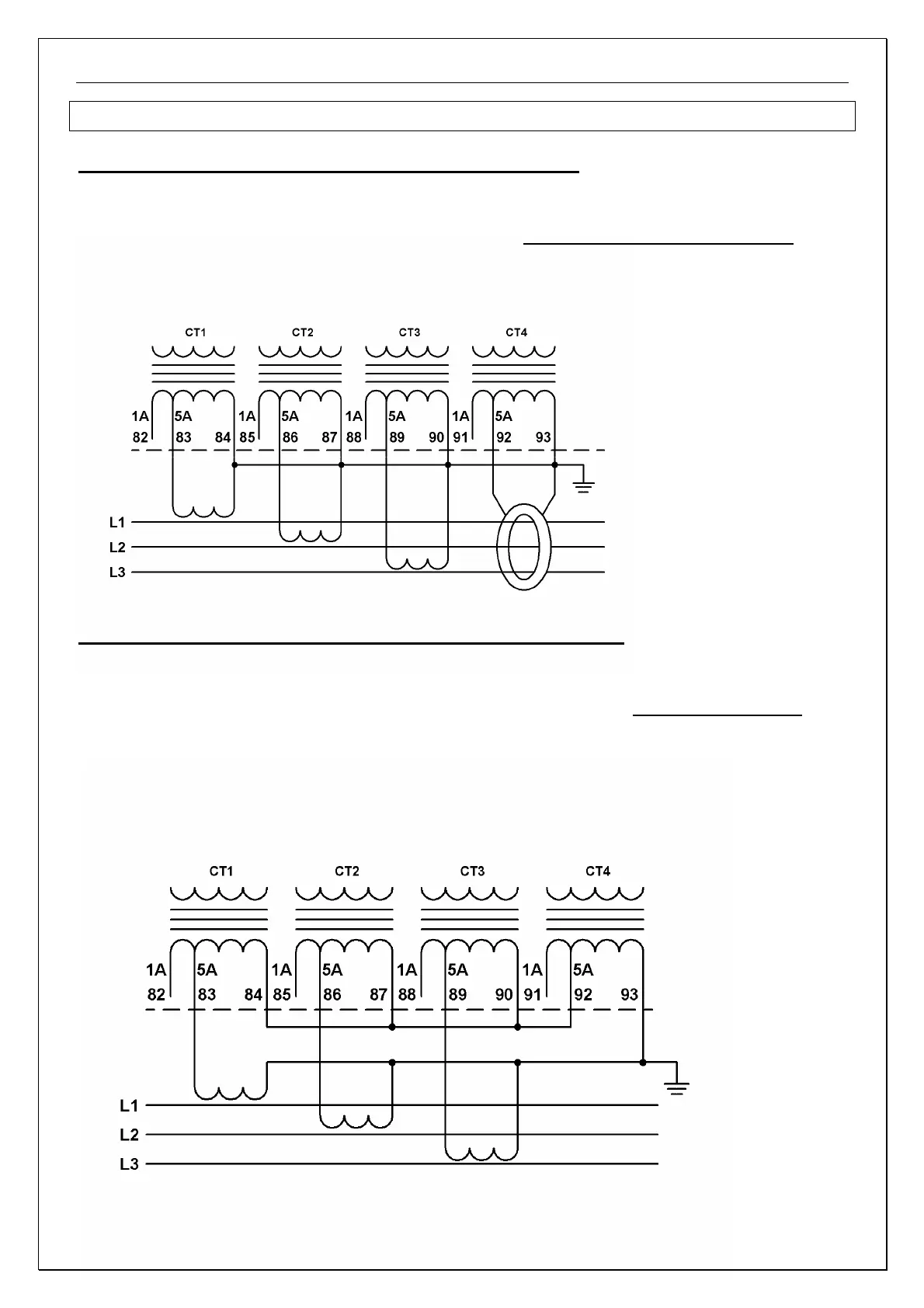
"C/T" WIRING DIAGRAMS
Three "C/T"s + Ground Fault Core Balance "C/T"
It is the preferred connection. It drawback is that a relatively large Core Balance transformer is required.
In the following drawings, the 5A inputs are used and the 1A are left open.
In this diagram terminal 92 which is the Ground Fault input current gets the sum of the three phase currents. If there
is no ground fault leakage current in the motor or cables, this current equals 0.
Three "C/T's" in a Residual Ground Fault Connection
When Core Balance "C/T" is not used and ground fault protection is required, use the residual Ground Fault
Connection.
In this diagram terminal 92 which is the Ground Fault input current, receives the sum of the "C/T" outputs of the
phase currents.
Ideally, if there is no ground fault leakage current, this current equals 0. Since "C/T"s may saturate slightly during
starting, their sum may not be 0 even when there is no leakage current to ground in the motor (or cables).
Note: In System Parameter page, the G/F DURING START setting parameter, is designed to significantly increase
the G/F level, during starting (same level for alarm and for trip) to prevent nuisance alarming and / or tripping.
For Residual Connection, It is recommended to leave the value in its default value which is 100% of FLC.