SET PAGE - MENUS
Page 46 of 67
Cool T Run
This is the Cooling Time Constant for a running motor. When motor current is below the Overload Pickup value,
Thermal Capacity is exponentially reduced, simulating motor cooling. Two different cooling time constants must
be used. Cooling time constant is significantly larger for a stopped motor.
Cool T Stop
This is the Cooling Time Constant for a stopped motor. When motor is stopped, Thermal Capacity is
exponentially reduced, simulating motor cooling. Normally, Cool Time Stop is 3 – 6 times larger than the Cool
Tow Run.
K Unbal Bias (Unbalance Bias Factor)
Unbalanced currents cause additional motor (mainly Rotor) heating. Unbalanced currents cause negative
rotating field, which generates rotor voltages and currents at twice the rated frequency. Further heating is
caused as a result of the Skin Effect, which causes significant increase of rotor resistance. The Skin Effect is
caused by the high frequency induced by the negative sequence field (compared to a frequency of
approximately 1Hz, caused by the positive sequence field).
This additional heating is entered into the thermal model using the K Unbal Bias. This factor changes the value
of the motor equivalent current (LEQ) used as the input current for the thermal model.
LEQ is given by:
LEQ = I% * √ (1 + K * (I
N
/I
P
) ²)
Where: I% - Motor RMS (average of the three phases) current
I
N
- Negative sequence Current
I
P
- Positive Sequence current
K - The above Unbalance Bias Factor
LEQ – Equivalent current, which takes into consideration the negative sequence extra heating.
RTD Bias
The Thermal model, as explained up to this point is based on current measurements only. It assumes normal
ambient working temperature of approximately 40°C. If the ambient temperature is higher, or if forced and
natural cooling of the motor is malfunctioning, the winding temperature can be significantly increased.
The RTD Bias is a possible way to take the actual winding temperature into consideration. The RTD are
relatively slow elements, however they sense accurately the real temperature of the windings. Therefore, the
RTD measurement can be used to correct the thermal model for slow motor heating, according to the actual
winding temperature. The first parameter RTD Bias allows to disable RTD Bias, to use RTD1..3 or to use
RTD1..6 for the temperature bias.
Note that when enabled, the RTD BIAS can only increase the Thermal Capacity value. It can never decrease it.
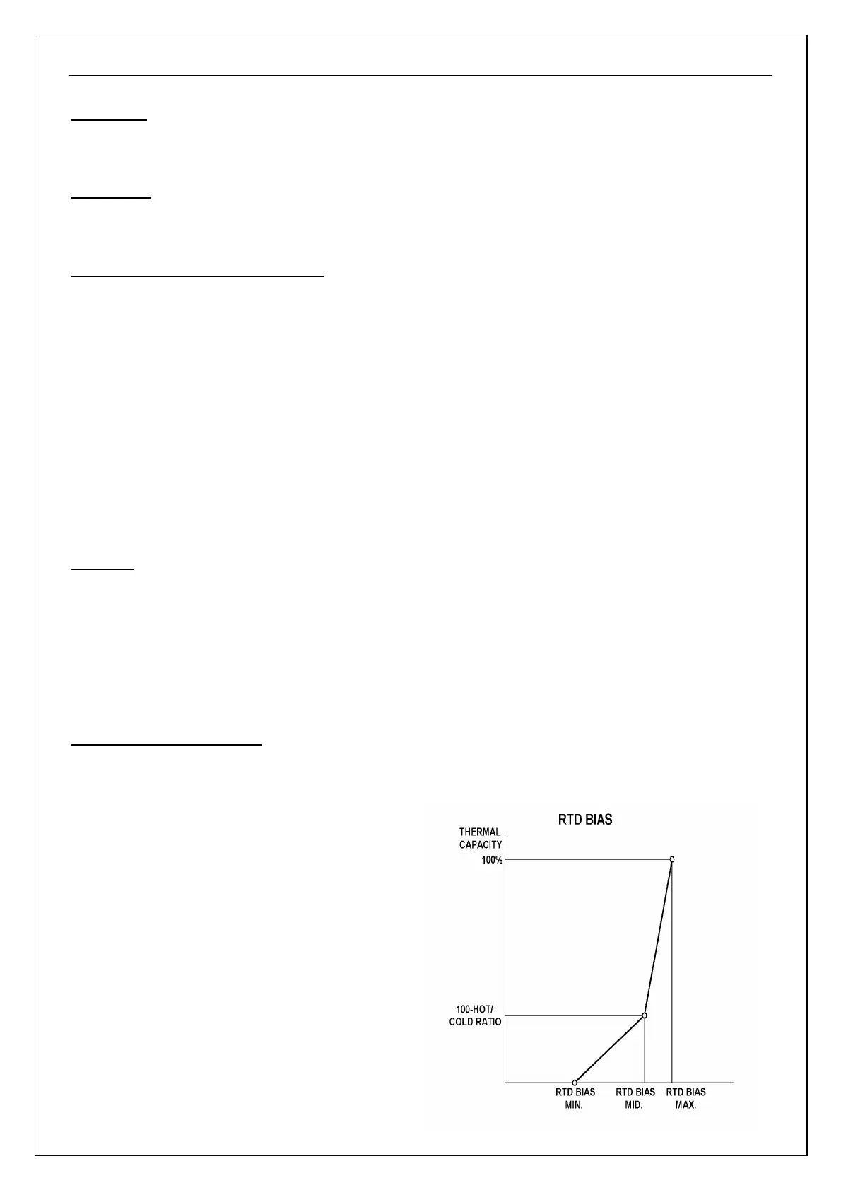
RTD Min, RTD Mid, RTD Max
RTD Bias is entered to the thermal model by means of the three following parameters: RTD Min, RTD Mid, RTD
Max. The RTD Bias curve is created by two straight lines drawn between the following three points.
First point (RTD Min,0): RTD Min is the (horizontal) Minimum Bias temperature. Below this temperature the
RTD Bias has no effect on the thermal model.
Second point (RTD Mid,100-Hot_Cold_Ratio): RTD
Mid is the normal expected working temperature with
100% load. At this point, the thermal capacity should
be 100 – Hot/Cold ratio.
Third point (RTD Max,100): RTD Max is the maximum
allowed working temperature. At this point, the thermal
capacity should be 100%.
When the overload thermal capacity (including
Unbalance Bias), is lower than the thermal capacity
dictated by the RTD Bias, it will be automatically
increased to the value of the RTD Bias curve value.
Note: If RTD temp is equal or above RTD Max the
Thermal capacity will be increased to slightly below
100%. This is to prevent Overload Trip, if the value of
the equivalent current is below Overload Pickup value.
Normally, RTD trip should occur at or before this point.