EasyManuals Logo

SOLIS S6 Series User Manual

SOLIS S6 Series
91 pages
To Next Page IconTo Next Page
To Previous Page IconTo Previous Page
Page #26 background imageLoading...
Page #26 background image
User Manual
NOTE
After crimping the terminal to the wire, inspect the connection to ensure the
terminal is solidly crimped to the wire.
5. Remove the M10 screw from the heat sink ground point.
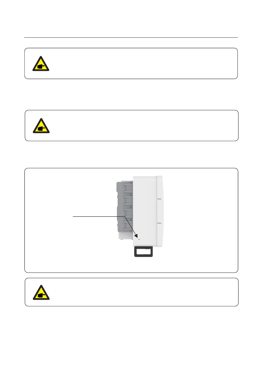
Figure 3.19 Fixed cable
To reduce corrosion, apply silicone or paint to the screw after ground cable
has been installed.
NOTE
4. Insert the stripped wire into the OT terminal crimping area and crimp with a hydraulic
crimp tool. (see Figure 3.18)
6. Connect the grounding cable to the grounding point on the heat sink, and tighten the
grounding screw, Torque is 4.4-6.0 ft.lbs. (see figure 3.19)
3. Installation
21
NOTE
B (insulation stripping length) is 2mm-3mm longer than A (OT cable
terminal crimping area).
Grounding screw
Torque4.6-6.0 ft.lbs

Table of Contents

Other manuals for SOLIS S6 Series

Questions and Answers:

Question and Answer IconNeed help?

Do you have a question about the SOLIS S6 Series and is the answer not in the manual?

SOLIS S6 Series Specifications

General IconGeneral
Number of MPPTs2
THDi<3%
DC SwitchYes
Max. AC Output Power6000W
Rated AC Output Power6000W
Max. AC Apparent Power6000VA
Rated Grid Voltage230V
Grid Voltage Range180V-280V
Rated Grid Frequency50Hz/60Hz
Grid Frequency Range45-55Hz / 55-65Hz
ProtectionDC Reverse-Polarity Protection, AC Short-Circuit Protection
Operating Temperature Range-25°C to 60°C
CoolingNatural Cooling
CommunicationWiFi/GPRS

Related product manuals