EasyManuals Logo

SOLIS S6 Series User Manual

SOLIS S6 Series
91 pages
To Next Page IconTo Next Page
To Previous Page IconTo Previous Page
Page #25 background imageLoading...
Page #25 background image
User Manual
3.4.1 Grounding
The inverter must be grounded for safety. Two methods are provided.
1. Connect the AC grounding cable. (See Section 3.4.3)
2. Connect the equipment grounding terminal on the heatsink described below.
1. It is recommended to use copper wire for the chassis ground. Either solid conductor or
stranded wire is acceptable. Refer to local code standard for wire sizing.
2. Attach OT terminal: M10.
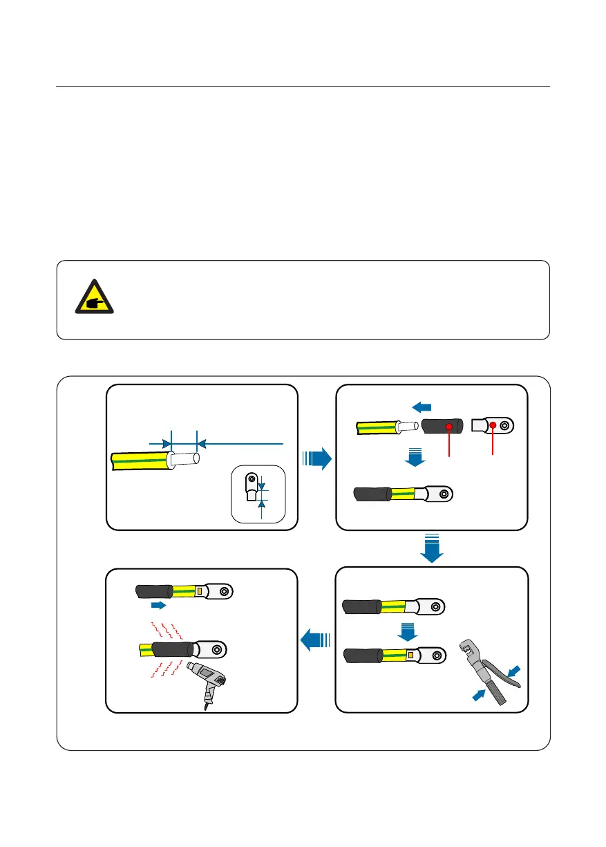
To connect the grounding terminal on the heat sink, please follow the steps below:
NOTE
3. Strip the ground cable insulation to a suitable length. (see Figure 3.18)
Figure 3.18 Suitable length
For multiple inverters in parallel , all inverters should be connected to the
same ground point to eliminate the possibility of a voltage potential existing
between inverter grounds.
3. Installation
20
A
B = A + (2~3)mm
1
2

Table of Contents

Other manuals for SOLIS S6 Series

Questions and Answers:

Question and Answer IconNeed help?

Do you have a question about the SOLIS S6 Series and is the answer not in the manual?

SOLIS S6 Series Specifications

General IconGeneral
Number of MPPTs2
THDi<3%
DC SwitchYes
Max. AC Output Power6000W
Rated AC Output Power6000W
Max. AC Apparent Power6000VA
Rated Grid Voltage230V
Grid Voltage Range180V-280V
Rated Grid Frequency50Hz/60Hz
Grid Frequency Range45-55Hz / 55-65Hz
ProtectionDC Reverse-Polarity Protection, AC Short-Circuit Protection
Operating Temperature Range-25°C to 60°C
CoolingNatural Cooling
CommunicationWiFi/GPRS

Related product manuals