User Manual
3.4 Electrical Connections
The electrical connection of the inverter must follow the steps listed below:
1. Switch the Grid Supply Main Switch (AC) OFF and LOTO the Main Switch.
2. Switch the DC Switch to OFF position.
3. Connect the inverter to the grid.
4. Assemble PV connector and connect to the Inverter.
Inverter design uses PV style quick-connect terminal. The inverter cover does not need to
be opened during DC electrical connection. The labels located on the bottom of the inverter
are described below in table 3.1. All electrical connections must be in accordance with local
or national standard.
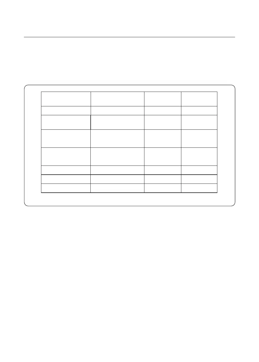
Table 3.1 Electrical connections
Parts
Connection Cable size
Torque
DC terminal
Ground terminal
Internal
Grid terminal
RS-485 terminal
RJ45 terminal
COM terminal
PV strings
AC ground
Grid
Communication cable
Communication cable
Wi-Fi/Cellular stick
12-8 AWG
4-3/0 AWG
(Max 250MCM)
4-3/0 AWG
(Max 250MCM)
22-12 AWG
Network cable
NA
11-15 ft.lbs
11-15 ft.lbs
0.44 ft.lbs
NA
NA
NA
3. Installation
19
Ground terminal
External
Equipment Ground
Local Code 4.4-6.0 ft.lbs