MPI-540 ● MPI-540-PV – BRIEF USER MANUAL
Fig. 3.5
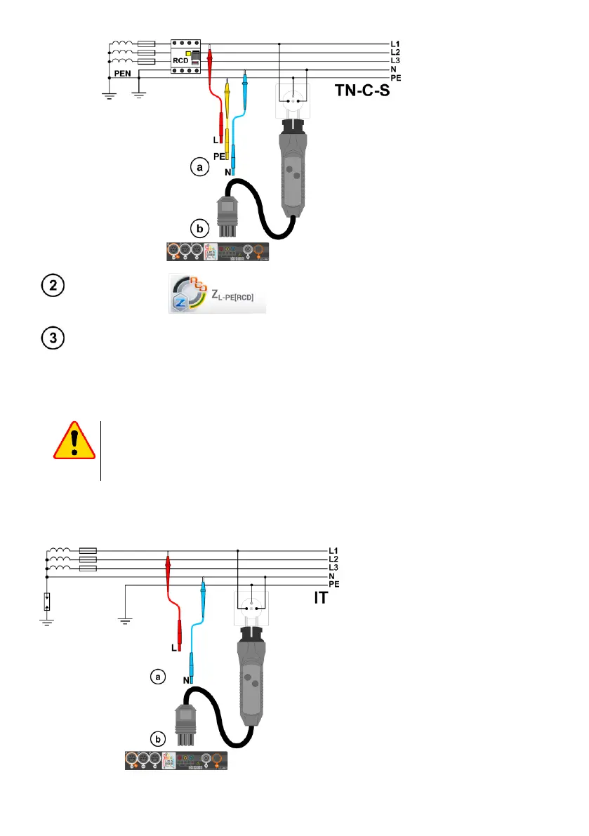
Measurement in the
TN-C-S system
Select other settings and perform the measurement using the START button on the device.
3.2.4 Measurement of fault loop impedance in IT networks
Before performing the measurements select the appropriate network type in the Measurement set-
tings menu.
NOTE!
After selecting an IT type network, the function of the contact electrode is inactive.
When attempting to perform the Z
L-PE
and Z
L-PE[RCD]
measurement a message will
appear informing that the measurement is impossible.
The manner of connecting the device to the installation is shown in Fig. 3.6.
The manner of performing the fault loop measurements is described in section 3.2.1.
Operating voltage range: 95 V … 440 V.
Fig. 3.6 Measurement in the IT
system

 Loading...


