MPI-540 ● MPI-540-PV – BRIEF USER MANUAL
3.17 Short circuit DC current I
SC
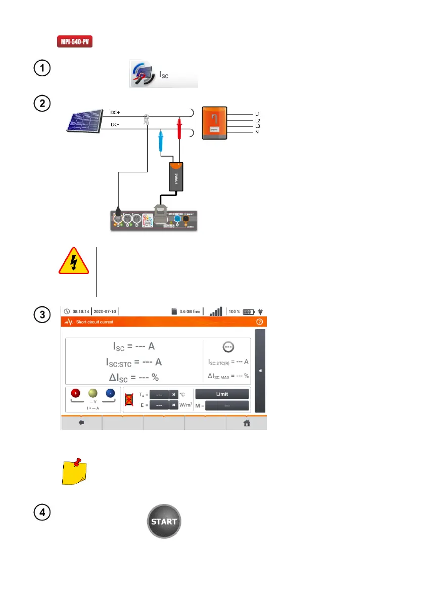
Select item I
SC
, to call up the
measurement screen. Then re-
set the clamp (sec. 3.19).
Turn off the inverter or discon-
nect it from the tested object.
Connect the meter to the chain of
PV modules using PVM-1 adapt-
er and adapters of MC4 connect-
ors The following parameters will
be measured:
I
SC
– short-circuit current
I
SC:STC
– short circuit current af-
ter conversion for STC* con-
ditions,
ΔI
SC
– difference of short-circuit
current (measured and con-
verted to STC conditions) and
the same current declared by
the producer of the panel, al-
so converted to STC.
*STC (Standard Test Conditions) – ref-
erence conditions, for which the
manufacturer provides all the param-
eters of the modules.
WARNING
Do not disconnect MC4 connectors when the load
current of working inverter flows through them. This
may cause arcing and danger to the user!
Enter the test parameters:
T
A
– ambient temperature, if the
source temperature meas-
urement = air (sec. 2.2.1),
T
PV
– module temperature, if the
source of temperature meas-
urement = module (sec.
2.2.1),
E – irradiance,
Limit – setting of ΔI
SC MAX
val-
ues,
M – photovoltaic module select-
ed from the meter database
(sec. 2.2.2).
In addition, the screen displays
the following:
I
SC:STC(R)
– short-circuit current
in STC conditions, as de-
clared by the manufacturer,
ΔI
SC MAX
– limit ΔI
SC
set.
Parameters T
A
, T
PV
, E come from the irradiance meter,
if it is connected to the meter. See also sec. 2.3.2.
If necessary, reset the clamps
again. Press START to start
the measurement.

 Loading...


