Manual Integrator Supercal 531 06-06-2011 66
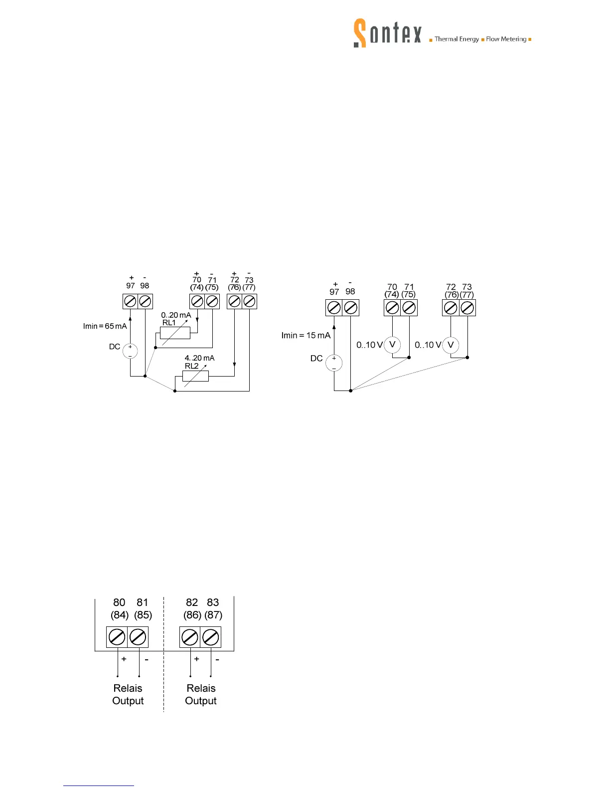
Analogue module with two outputs 0...20 mA, 4..20 mA or 0..10 VDC (see 6.2.1)
2 inputs: 2 (external voltage supply)
Voltage supply 12 VAC or 12...24 VDC (external)
Tolerances 12 VDC (0 %), 24 VDC (+ 35%)
2 outputs
Analogue signal 0...20 mA, 4..20 mA (in overflow 3,5..24 mA)
Voltage signal 0...10 VDC, 2…10 VDC
Burden RL (max.) = 650 Ω at 24 VDC
RL (max.) = 350 Ω at 12 VDC
Resolution 16 Bit (15 Bit in overflow)
Maximum converter error 0.02 % of final value
Circuit diagram:
Factory setting (mains operation) switch-over via flip switch (voltage operation)
Relay module (see 6.2.2)
Outputs 2 (freely selectable)
Max. switching voltage, peak 60 V AC/DC
Max. constant current 400 mA
Surge current (100 ms) 1'000 mA
Max. power dissipation 500 mW
Max. forward resistance 2,5 Ω
Typical output capacitance 150 pF
Max. frequency 100 Hz
Pulse duration 5..400 ms possible in steps of 1ms
Error status closed (no error)
Alarm condition open (no alarm)
Circuit diagram: