15
Tape Speed Adjustment DECK A
Procedure:
Turn the power switch on.
Mode: Playback (FWD)
1. Insert the WS-48B into the deck A and the blank tape into the
deck B.
2. Press the [HI-SPEED DUBBING] button and X button.
Then at HIGH speed dubbing.
3. Adjust RV652 on the AUDIO board do that frequency counter
reads 6,000 ± 180 Hz.
4. Press the x (TAPE A or B) button to stop the HIGH speed
dubbing.
5. Press the [REC ], X and Y button.
Then at NORMAL speed dubbing.
6. Adjust RV651 on the AUDIO board so that frequency counter
reads 3,000 ± 90 Hz.
7. Press the
x (TAPE A or B) button to stop the NORMAL speed
dubbing.
8. Frequency difference between deck A and deck B the begin-
ning of the tape should be within ± 1.5%.
Adjustment Location: AUDIO and MAIN boards
Sample Value of Wow and flutter: 0.3% or less W. RMS (JIS)
(WS-48B)
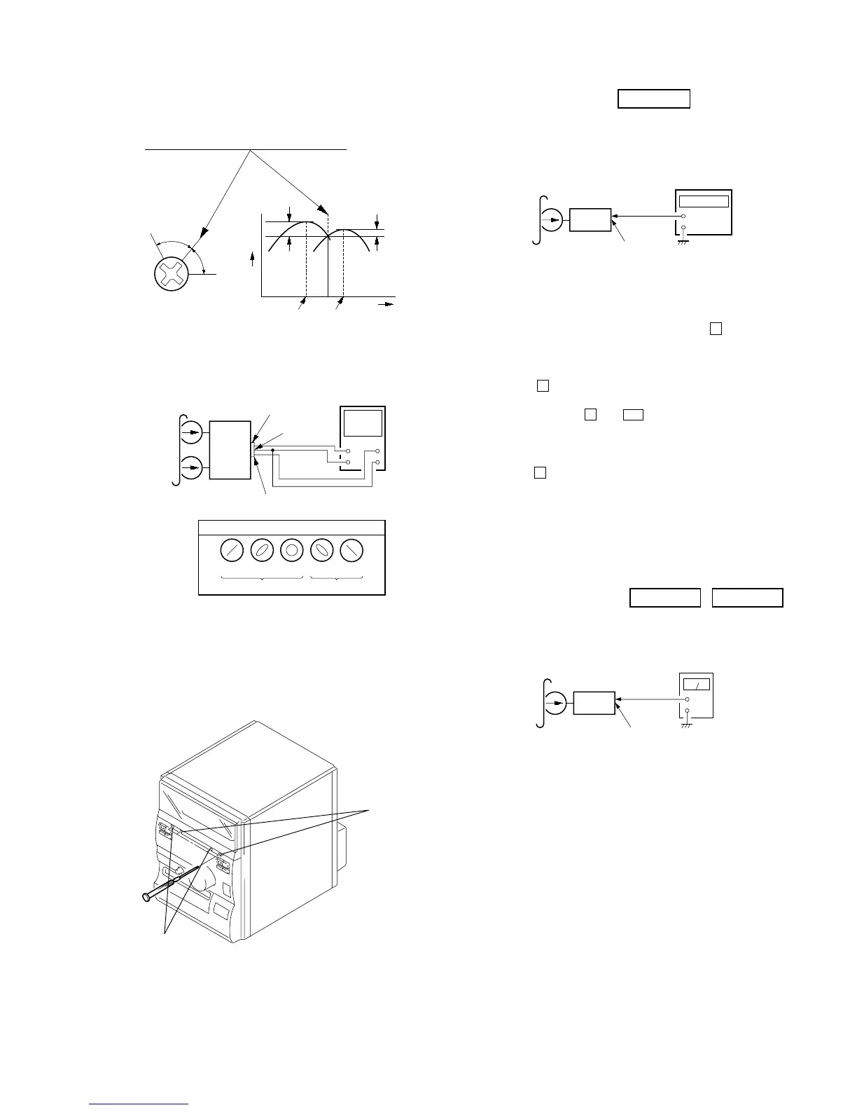
Playback level Adjustment
Procedure:
Mode: Playback (FWD)
Deck A is RV311 (L-CH) and RV411 (R-CH), Deck B is RV301
(L-CH) and RV401 (R-CH) so that adjustment within adjustment
level as follows.
Adjustment Level:
IC401 PB level: 301.5 to 338.3 mV (–8.2 to –7.2 dB) level
difference between the channels: within ± 0.5 dB
Adjustment Location: AUDIO and MAIN boards
level meter
1. Mode: Playback (FWD)
2. Turn the adjustment screw and check output peaks. If the peaks
do not match for L-CH and R-CH, turn the adjustment screw
so that outputs match within 1dB of peak.
3. Mode: Playback (FWD)
4. Repeat steps 1 to 3 in playback (REV) mode.
5. After the adjustments, apply suitable locking compound to the
pats adjusted.
Adjustment Location: Record/Playback Head (Deck A and B)
and MAIN board.
Screw
position
L-CH
peak
within
1dB
output
level
L-CH
peak
R-CH
peak
within
1dB
Screw
position
R-CH
peak
MAIN
board
IC401
set
test tape
P-4-A100
(10 kHz, –10 dB)
pin
eg
oscilloscope
L-CH
R-CH
V
H
waveform of oscilloscope
in phase 45 °
90 ° 135 ° 180 °
good
wrong
pin rs
pin 8
L
R
revers