16
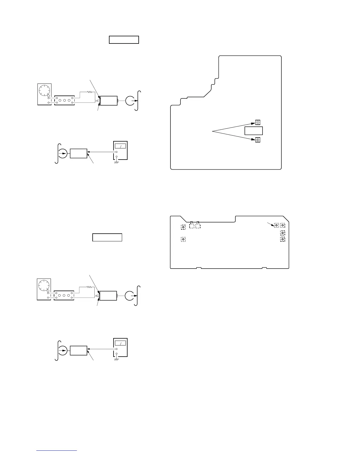
Record bias Current Adjustment
Procedure:
1. Mode: Record
2. Mode: Playback
Confirm playback the signal recorded in step 1 become adjustable
limits as follows.
If these levels do not adjustable limits, adjustment the RV341 (L-
CH) and RV441 (R-CH) on the AUDIO board to repeat steps 1
and 2.
Adjustable limits: Playback output of 315 Hz to playback output
of 10 kHz: 0 ± 0.5 dB
Adjustment Location: AUDIO and MAIN boards
Record Level Adjustment
Procedure:
1. Mode: Record
2. Mode: Playback
Confirm playback the signal recorded in step 1 become adjustable
limits as follows.
If these levels do not adjustable limits, adjustment the RV301 (L-
CH) and RV351 (R-CH) on the MAIN board to repeat steps 1 and
2.
Adjustable limits:
IC401 PB level: 36.7 to 41.1 mV (–26.5 to –25.5 dB)
Adjustment Location: MAIN board
DECK B
attenuator
set
Pin 6 (L-CH) of IC401 on the MAIN board.
Pin ej (R-CH) of IC401 on the MAIN board.
1) 315 Hz
2) 10 kHz
50 mV (–23.8 dB)
Pin rs (GND) of IC401 on the MAIN
board.
600 Ω
blank tape
CN-123
AF OSC
+
–
set
recorded
portion
IC401 (Pin 8 : L-CH)
DECK B
set
Pin 6 (L-CH) of IC401 on the MAIN board.
Pin
ej (R-CH) of IC401 on the MAIN board.
315 Hz, 50 mV (–23.8 dB)
blank tape
CS-123
Pin
rs (GND) of IC401 on the MAIN board.
600 Ω
attenuator
AF OSC
+
–
set
recorded
portion
IC401 (Pin 8 : L-CH)
Adjustment Location:
– MAIN BOARD (Component Side) –
– AUDIO BOARD (Conductor Side) –
* As the adjustment parts is mounted on the component side, ad-
just it through a hole in the AUDIO board form conductor side.
(Except RV431, 441)
RV651
RV311 L
RV411 R
RV652
(NORMAL) (HIGH)
TAPE SPEED
PB
LEVEL
– DECK A –– DECK B –
RECORD
BIAS CURRENT
RV341
RV441
RV301
RV401
L
R
PB LEVEL
RL
RV351
IC401
RV301
RECORD
LEVEL