Do you have a question about the Sony HCD-EC79i and is the answer not in the manual?
Procedures for safely handling optical pick-up blocks and base units during repair.
Guidelines for safely checking laser diode emission from the optical pick-up.
Information and precautions for using unleaded solder during repairs.
Steps to release the disc tray lock for specific models.
Specific instruction for replacing the loading board on certain models.
Procedures for performing safety checks, including AC leakage tests.
Warning about critical components identified for safe operation.
Initial setup instructions for antennas, speakers, power, iPod, and volume.
Instructions for connecting and using an iPod, adjusting volume, and using headphones.
Procedures for setting the clock and changing display modes.
Detailed instructions for playing CDs and MP3s, including modes and notes.
Guidance on tuning and presetting FM/AM radio stations.
Connecting external audio sources and adjusting sound settings like DSGX and subwoofer.
Instructions for using the Sleep Timer and Play Timer functions.
Step-by-step instructions for disassembling US and Canadian models.
Step-by-step instructions for disassembling UK, Australian, and EC99i models.
Clears all data, including preset data, to initial conditions.
Activates LEDs and segments on the liquid crystal display for testing.
Displays date and version, then destination and model name.
Tests all buttons and the volume dial, displaying their status.
Enables CD repeat playback for unlimited times by canceling the 5-time limit.
Locks the disc tray for antitheft purposes in shops.
Controls power supply on/off state for the CD tray.
Switches the AM tuning interval between 9 kHz and 10 kHz.
Checks optical pick-up system operations and allows mode entry/exit.
Displays past errors of the optical pick-up system as BD Errors.
Moves the SLED and controls optical pick-up laser power on/off.
Enters factory mode for settings like S character mode and RF gain.
Checks focus bias when the optical pick-up block is replaced.
Covers FM frequency coverage, tracking, detector, auto-stop, and AM adjustments.
Provides a block diagram illustrating the CD and Tuner sections of the unit.
Illustrates the block diagram for the main section of the unit, including audio and power paths.
Shows the block diagram for the panel controls and the power supply system.
Common notes for understanding printed wiring boards and schematic diagrams, including board locations.
Detailed view of the CD board's printed wiring, showing component layout.
Electrical schematic of the CD board, detailing component connections and IC functions.
Electrical schematic of the main board, illustrating its internal connections and components.
Electrical schematic of the main board, continuing the illustration from the previous page.
Layout of the main board's printed wiring, showing component placement.
Printed wiring board layouts for the 2CH-4CH and 3CH amplifier sections.
Electrical schematic for the 2-channel to 4-channel amplifier board.
Electrical schematic for the 3-channel amplifier board, specific to the EC99i model.
Layout of the printed wiring for the panel section, showing component placement.
Electrical schematic for the panel section, detailing its circuitry.
Printed wiring board layouts for audio input/output, key controls, and power supply.
Electrical schematic for audio input/output, key controls, and power supply sections.
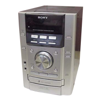
Exploded view of the HCD-EC69i unit, showing overall assembly and parts.
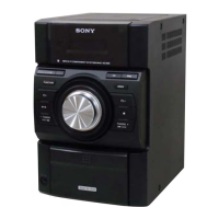
Exploded view of the HCD-EC79i/EC99i units, showing overall assembly and parts.
Exploded view of the top panel for US and Canadian models.
Exploded view of the top panel for UK, Australian, and EC99i models.
Exploded view of the front panel, detailing its components and assembly.
Exploded view of the iPod dock assembly, showing its parts and connections.
Exploded view of the main board and chassis for the HCD-EC69i model.
Exploded view of the main board for the HCD-EC79i/EC99i models.
Exploded view of the chassis for the HCD-EC79i/EC99i units.
List of electrical components for the 2CH-4CH amplifier board, categorized by type.
List of electrical components for the 3CH amplifier board, including resistors and capacitors.
Lists components for the 3CH amplifier board and CD board, including connectors, diodes, ICs, and resistors.
Parts list for CD, IP, JACK, KEY, LOADING, and PT-SINGLE boards, including resistors, switches, and transformers.
Parts list for IP, JACK, KEY, LOADING, and MAIN boards, including switches, capacitors, and diodes.
Detailed list of capacitors for the main board, specifying type, value, and voltage.
Lists transistors, coils, inductors, and other components for the main board.
Comprehensive list of resistors for the main board, including values and wattage.
Continues the list of resistors for the main board, detailing type, value, and tolerance.
Lists relays, terminals, vibrator, capacitors, and transformers for the main board.
Lists ICs, diodes, transistors, and resistors for the panel board.
Lists switches, vibrator, capacitors, connectors, and transformers for the panel board.
Lists accessories such as adapters and plugs for the panel board.
Details the version history of the service manual, including dates and revision descriptions.