29
HCD-GNZ7D/GNZ8D/GNZ9D
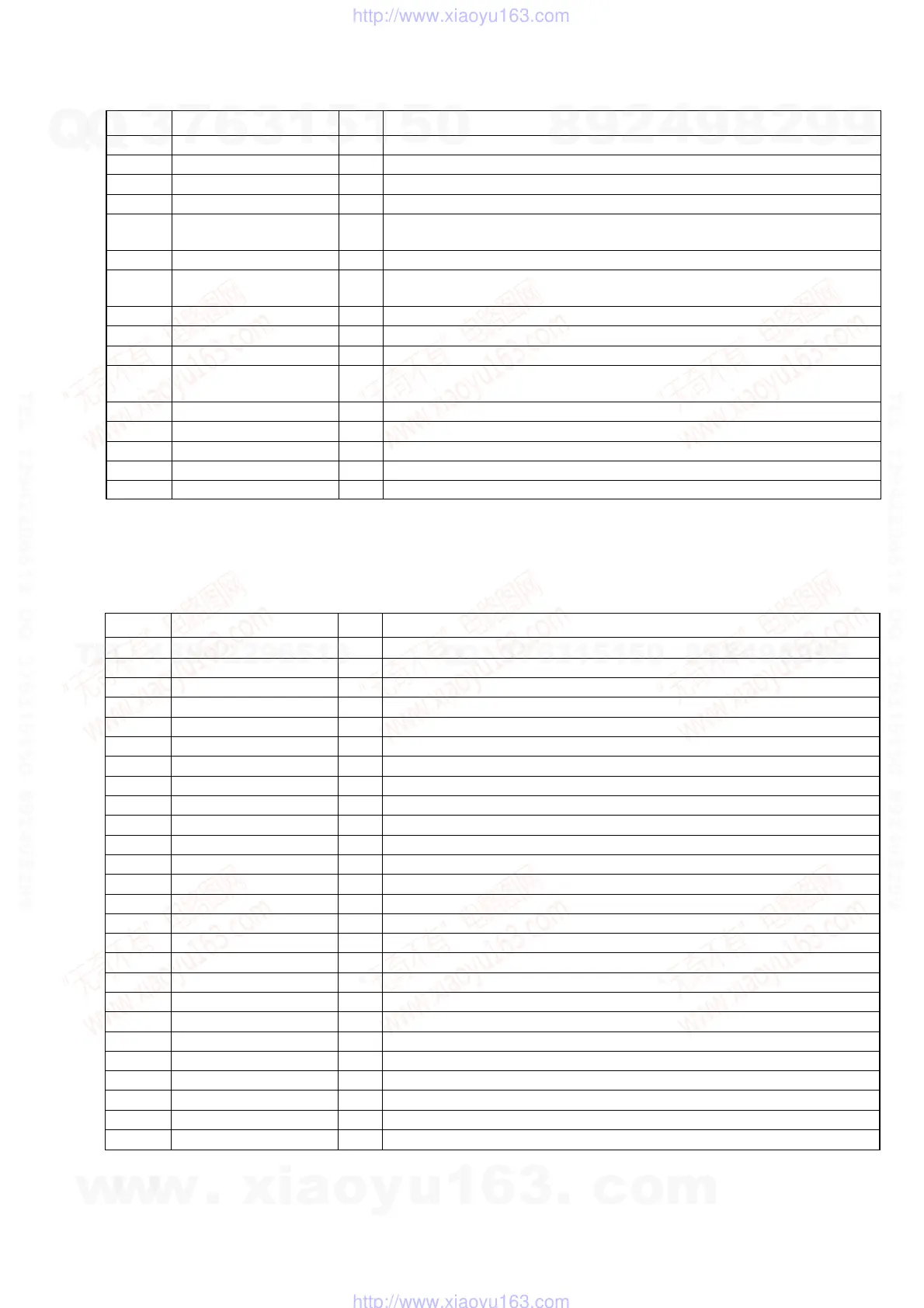
Pin No. Pin Name I/O Pin Description
83 SHUT (A) I Protect detect signal input (A deck)
84 SHUT (B) I Protect detect signal input (B deck)
85 B HALF/REC I B deck HALF signal input/Record signal input (A deck and B deck)
86 BIAS O Bias on/off signal output
87
KARAOKE/
I
MTK KARAOKE mode signal input
MTK M REQ MTK mute request signal input
88 VACS/ILLUMI I VACS and illumination (L+R) control signal input
89
VOL (A) & (B)/
I
Volume A and B control signal input
SW IN Sub woofer control signal input
90 SPEC IN I Specification signal input
91 MODEL IN I Serial line up signal input
92 to 94 KEY2 to KEY0 I Key signal input
95
CDM EJECT/
I
CD mechanism eject detect signal input
PROTECT Protect detect signal input
96 AVSS — Ground pin
97 CDM ENC0/1/2 I CD mechanism switch signal input
98 VREF — Voltage reference pin
99 AVCC — Power supply pin (+3.3 V)
100 CDM TBL SENS I CD mechanism table sensor detect signal input
IC102 BH2210FV (SIGNAL IN/OUT CONTROL) (PANEL BOARD (2/2))
Pin No. Pin Name I/O Pin Description
1 CTLIO I IN/OUT control port (Fixed at “H” in this set.)
2 RSTB I Reset signal input
3 CLK I Serial clock signal input
4LATCH I Serial latch signal input
5 STBY RELAY O Standby relay on/off signal output “H”: On, “L”: Off
6FAN ON/OFF O Fan on/off signal output “H”: Off, “L”: On
7FRONT RELAY O Front relay on/off signal output “H”: On, “L”: Off
8TA MUTE O TA line mute on/off signal output “H”: Off, “L”: On
9 HP MUTE O Headphones mute on/off signal output “H”: Off, “L”: On
10 AU-OUT MUTE O Audio out mute on/off signal output “H”: Off, “L”: On
11 SW MUTE O Subwoofer mute on/off signal output “H”: Off, “L”: On
12 FAN CTRL O FAN control signal output “L”: Off
13 to 15 NO USE O Not used. (Open)
16 NO USE O Not used. (Fixed at “L”.)
17 TBL POS O CD mechanism table position control signal output
18 TBL NEG O CD mechanism table NEG control signal output
19 LOD POS O CD mechanism table loading position control signal output
20 LOD NEG O CD mechanism table NEG control signal output
21 PB/REC O Tape playback/record signal output “H”: REC, “L”: PB
22 REAR RELAY O Rear relay on/off signal output “H”: On, “L”: Off
23 SW RELAY O Subwoofer relay on/off signal output “H”: On, “L”: Off
24 CAPM SW O Capstan motor on/off signal output “H”: On, “L”: Off
25 DO2 O Not used. (Open)
26 DI1 I Serial data signal input
27 VSS — Ground pin
28 VDD — Power supply pin (+3 V)
w
w
w
.
x
i
a
o
y
u
1
6
3
.
c
o
m
Q
Q
3
7
6
3
1
5
1
5
0
9
9
2
8
9
4
2
9
8
T
E
L
1
3
9
4
2
2
9
6
5
1
3
9
9
2
8
9
4
2
9
8
0
5
1
5
1
3
6
7
3
Q
Q
TEL 13942296513 QQ 376315150 892498299
TEL 13942296513 QQ 376315150 892498299
http://www.xiaoyu163.com
http://www.xiaoyu163.com
 Loading...