17
HCD-M700
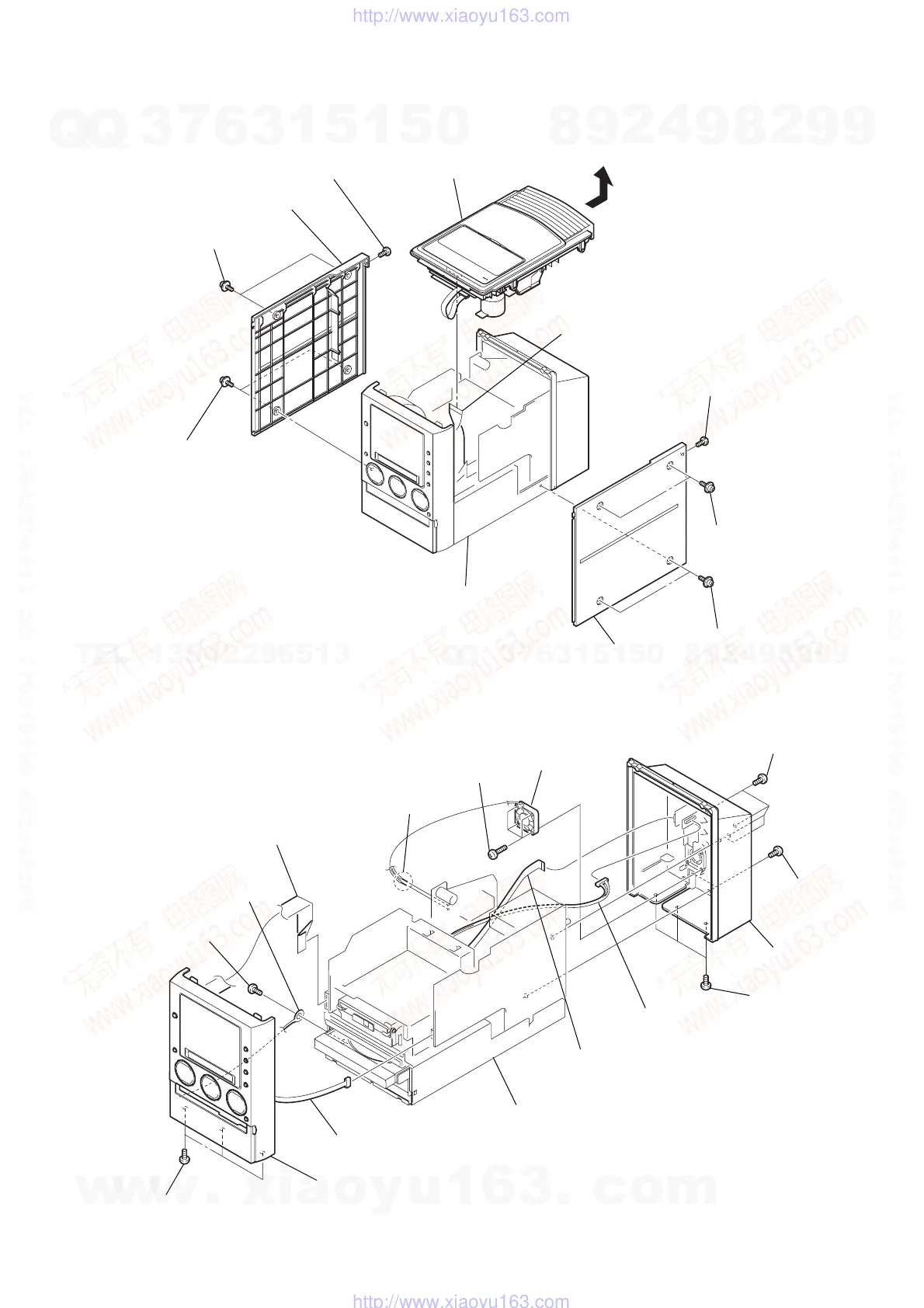
3-2. Front Panel Section, Back Panel Section
3-1. Case (R), Case (L), Top Cover Section
Note: Follow the disassembly procedure in the numerical order given.
chassis section
9
qa
top cover section
q;
flexible flat cable
(CN301)
3
screw (+BVTP 3
×
10)
7
screw (+BVTP 3
×
10)
2
two
screws
(3
×
10
case 3 TP2
6
two
screws
(3
×
10
case 3 TP2)
1
two
screws
(3
×
8
case 3 TP2)
5
two
screws
(3
×
8
case 3 TP2)
4
case (R)
8
case (L)
5
flexible flat cable
(
CN609)
qf
flexible flat cable
(CN604)
qa
earth wire
qs
connector (CN304)
6
connector (CN610)
qg
front panel section
4
back panel section
9
DC fan
1
four
screws (+BVTP 3
×
10)
7
four
screws (+BVTP 3
×
16)
qd
three
screws
(+BVTP 3
×
8
)
q;
screw
(+BVTP 3
×
8
)
3
three
screws
(+BVTP 3
×
8
)
2
two
screws
(+BVTP 3
×
8
)
chassis section
8
Remove the soldering.
w
w
w
.
x
i
a
o
y
u
1
6
3
.
c
o
m
Q
Q
3
7
6
3
1
5
1
5
0
9
9
2
8
9
4
2
9
8
T
E
L
1
3
9
4
2
2
9
6
5
1
3
9
9
2
8
9
4
2
9
8
0
5
1
5
1
3
6
7
3
Q
Q
TEL 13942296513 QQ 376315150 892498299
TEL 13942296513 QQ 376315150 892498299
http://www.xiaoyu163.com
http://www.xiaoyu163.com