angle
R-CH
peak
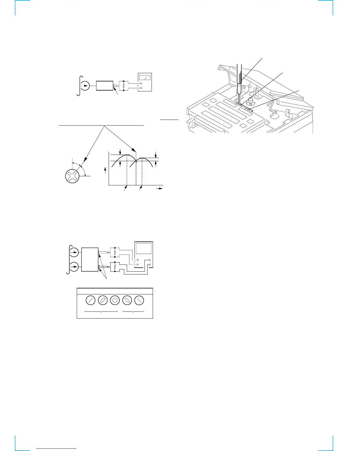
3. Phase Check
Mode: FWD/REV playback
4. After the adjustment, lock the screws with locking compound.
Record/Playback/Erase Head Azimuth Adjustment
Procedure:
1. Mode: FWD/REV playback
2. Turn the adjustment screw for the maximum output levels. If
these levels do not match, turn the adjustment screw
until both
of output levels match together within 1 dB.
Adjustment Location:
+
–
set
32 Ω
level meter
test tape
P-4-A100
(10 kHz, –10 dB)
i (headphones) jack (J301)
+
–
V
H
+
–
Screen pattern
set
L-CH
32 Ω
test tape
P-4-A100
(10 kHz, –10 dB)
i (headphones) jack (J301)
R-CH
32 Ω
oscilloscope
Good Wrong
in phase 45 ° 90 ° 135 ° 180 °
screwdriver
FWD
(forward)
REV
(reverse)