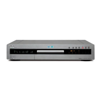
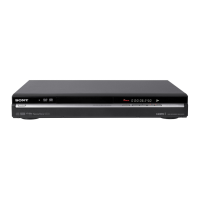
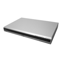
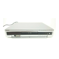
1-4
18
Step 3: Connecting the Video Cords
Step 3: Connecting the
Video Cords
Connect this recorder to your TV monitor, projector, or AV
amplifier (receiver) using a video cord. Select one of the
following patterns A through C, according to the input jack on
your TV monitor, projector, or AV amplifier (receiver). This will
enable you to view pictures. Audio connections are explained in
“Step 4: Connecting the Audio Cords” (page 19).
If you are connecting to a VCR
Connect your VCR to the LINE IN (VIDEO) jack on the
recorder (page 29).
A Connecting to a video input jack
Connect the yellow plug of the audio/video cord (supplied) to the
yellow (video) jacks. You will enjoy standard quality images.
Use the red and white plugs to connect to the audio input jacks
(page 20).
B Connecting to an S VIDEO input jack
Connect using an S VIDEO cord (not supplied). You will enjoy
high quality images.
C Connecting to component video
input jacks (Y, P
B
, P
R
)
Connect the component via the COMPONENT VIDEO OUT jacks
using a component video cord (not supplied) or three video cords
(not supplied) of the same kind and length. You will enjoy accurate
color reproduction and high quality images. If your TV accepts
progressive (480p) format signals, you must use this connection and
then press PROGRESSIVE on the front panel to accept progressive
video signals. See “Using the PROGRESSIVE button” (page 51) for
more information.
When connecting to a standard 4:3 screen TV
Depending on the disc, the image may not fit your TV screen. To
change the aspect ration, see page 94.
If your TV has a CONTROL S jack
You can control the recorder by operating the remote toward the
TV. This feature is convenient when you placed the recorder and
the TV away from each other.
After connecting the recorder to other equipment in pattern A,
B, or C above, connect the CONTROL S IN jack to your TV’s
CONTROL S (OUT) jack using a control S cord (not supplied).
Refer to the instructions supplied with the TV to be connected.
~
AC IN
S VIDEO
VIDEO
R-AUDIO-L
COMPONENT
VIDEO OUT
P
B
Y
P
R
S VIDEO
VIDEOR-AUDIO-L
1
3
1
2
VHF/UHF
IN
OUT
DIGITAL OUT
PCM/DTS/DOLBY DIGITAL
COAXIAL
OPTICAL
CONTROL S IN
LINE IN LINE OUT
LINE OUT
S VIDEO
VIDEO
R-AUDIO-L
1
2
AUDIO
INPUT
L
R
VIDEO
DVD recorder
to LINE OUT (VIDEO) 1 or 2
Audio/video cord (supplied)
TV, projector, or AV
amplifier (receiver)
: Signal flow
(yellow)
(yellow)
~
AC IN
S VIDEO
VIDEO
R-AUDIO-L
COMPONENT
VIDEO OUT
P
B
Y
P
R
S VIDEO
VIDEOR-AUDIO-L
1
3
1
2
VHF/UHF
IN
OUT
DIGITAL OUT
PCM/DTS/DOLBY DIGITAL
COAXIAL
OPTICAL
CONTROL S IN
LINE IN LINE OUT
INPUT
S VIDEO
LINE OUT
S VIDEO
VIDEO
R-AUDIO-L
1
2
DVD recorder
to LINE OUT (S VIDEO) 1 or 2
S VIDEO cord (not supplied)
TV, projector, or AV
amplifier (receiver)
: Signal flow
~
AC IN
S VIDEO
VIDEO
R-AUDIO-L
COMPONENT
VIDEO OUT
P
B
Y
P
R
S VIDEO
VIDEOR-AUDIO-L
1
3
1
2
VHF/UHF
IN
OUT
DIGITAL OUT
PCM/DTS/DOLBY DIGITAL
COAXIAL
OPTICAL
CONTROL S IN
LINE IN LINE OUT
PR
PB
Y
COMPONENT
VIDEO IN
COMPONENT
VIDEO OUT
P
B
Y
P
R
DVD recorder
to COMPONENT
VIDEO OUT
(green)
(blue)
(red)
(green)
(blue)
(red)
Component video
cord (not supplied)
TV, projector, or AV
amplifier (receiver)
: Signal flow
~
AC IN
S VIDEO
VIDEO
R-AUDIO-L
COMPONENT
VIDEO OUT
P
B
Y
P
R
S VIDEO
VIDEOR-AUDIO-L
1
3
1
2
VHF/UHF
IN
OUT
DIGITAL OUT
PCM/DTS/DOLBY DIGITAL
COAXIAL
OPTICAL
CONTROL S IN
LINE IN LINE OUT
CONTROL S IN
CONTROL S
DVD recorder
to CONTROL S IN
Control S cord (not supplied)
: Signal flow
TV
19
Step 4: Connecting the Audio Cords
Basic Hookups and Settings
Note
Consumers should note that not all high definition television sets are
fully compatible with this product and may cause artifacts to be
displayed in the picture. In the case of 480 progressive scan picture
problems, it is recommended that the user switch the connection to the
‘standard definition’ output. If there are questions regarding our TV set
compatibility with this model 480p DVD recorder, please contact our
customer service center.
Step 4: Connecting the
Audio Cords
Select the connection that best suits your system. Be sure to read
the instructions for the components you wish to connect.
*1
Manufactured under license from Dolby laboratories.
“Dolby,” “Pro Logic,” and the double-D symbol are trademarks of
Dolby Laboratories.
*2
“DTS” and “DTS Digital Out” are trademarks of Digital Theater
Systems, Inc.
Connection Your setup
TV
• Surround effects: Dynamic, Wide
Stereo amplifier (receiver)
and
two speakers
• Surround effects: Standard
MD deck/DAT deck
• Surround effects: None
AV amplifier (receiver) having a
Dolby Surround (Pro Logic)
decoder
*1
and 3 to 6 speakers
• Surround effects: Dolby Surround
(Pro Logic)
AV amplifier (receiver) with a
digital input jack having a Dolby
Digital or DTS
*2
decoder and 6
speakers
• Surround effects: Dolby Digital
(5.1ch), DTS (5.1ch)
A
B
C
D
,
continued
20
Step 4: Connecting the Audio Cords
Connecting to your TV
This connection will use your TV’s speakers for sound.
* The yellow plug is used for video signals (page 18).
z Hint
When connecting to a monaural TV, use a stereo-mono conversion cord
(not supplied). Connect the LINE OUT (R-AUDIO-L) 1/2 jacks to the
TV’s audio input jack.
Note
Do not connect the LINE IN (AUDIO L/R) jacks to your TV’s audio
output jacks at the same time.
Connecting to a stereo amplifier
(receiver) and 2 speakers/Connecting
to an MD deck or DAT deck
If your stereo amplifier (receiver) only has audio input jacks L
and R, use . If your amplifier (receiver) has a digital input
jack, or when connecting to an MD deck or DAT deck, use .
In this case, you can also connect the recorder directly to the MD
deck or DAT deck without using your stereo amplifier
(receiver).
z Hint
For connection , you can use the supplied audio/video cord instead
of using a separate stereo audio cord.
A
~
AC IN
S VIDEO
VIDEO
R-AUDIO-L
COMPONENT
VIDEO OUT
P
B
Y
P
R
S VIDEO
VIDEOR-AUDIO-L
1
3
1
2
VHF/UHF
IN
OUT
DIGITAL OUT
PCM/DTS/DOLBY DIGITAL
COAXIAL
OPTICAL
CONTROL S IN
LINE IN LINE OUT
LINE OUT
S VIDEO
VIDEO
R-AUDIO-L
1
2
A
AUDIO
INPUT
L
R
VIDEO
DVD recorder
to LINE OUT (R-AUDIO-L) 1 or 2
TV
(yellow)
(white)
(red)
(yellow)*
(white)
(red)
Audio/video cord
(supplied)
: Signal flow
B
B-1
B-2
~
AC IN
S VIDEO
VIDEO
R-AUDIO-L
COMPONENT
VIDEO OUT
P
B
Y
P
R
S VIDEO
VIDEOR-AUDIO-L
1
3
1
2
VHF/UHF
IN
OUT
DIGITAL OUT
PCM/DTS/DOLBY DIGITAL
COAXIAL
OPTICAL
CONTROL S IN
LINE IN LINE OUT
LINE OUT
S VIDEO
VIDEO
R-AUDIO-L
1
2
B-2 B-1
DIGITAL OUT
PCM/DTS/DOLBY DIGITAL
COAXIAL
OPTICAL
DVD recorder
Coaxial digital cord
(not supplied)
to DIGITAL OUT
(COAXIAL or OPTICAL)
or
to LINE OUT
(R-AUDIO-L)
1 or 2
(white)(red)
Stereo audio
cord (not
supplied)
(white)(red)
to audio input
Stereo amplifier (receiver)
MD deck/DAT deck
[Speakers]
Front (L)
Front (R)
to coaxial or optical
digital input
Optical digital cord
(not supplied)
: Signal flow
B-1
21
Step 4: Connecting the Audio Cords
Basic Hookups and Settings
Connecting to an AV amplifier
(receiver) having a Dolby Surround (Pro
Logic) decoder and 3 to 6 speakers
If your AV amplifier (receiver) only has L and R audio input
jacks, use . If your amplifier (receiver) has a digital input
jack, use .
You can enjoy Dolby Surround effects only when playing Dolby
Surround audio or multi-channel audio (Dolby Digital) discs.
z Hint
For correct speaker location, see the operating instructions of the
connected components.
Note
When connecting 6 speakers, replace the monaural rear speaker with a
center speaker, 2 rear speakers, and a subwoofer.
Connecting to an AV amplifier
(receiver) with a digital input jack and
6 speakers
If your AV amplifier (receiver) has a Dolby Digital or DTS
decoder and a digital input jack, use this connection. Note that
the surround sound effects of this recorder cannot be used with
this connection.
z Hint
For correct speaker location, see the operating instructions of the
connected components.
Note
After you have completed the connection, be sure to set “Dolby Digital”
to “Dolby Digital” and “DTS” to “On” under “Audio” in Easy Setup
(page 24). Otherwise, no sound or a loud noise will come from your
speakers.
C
C-1
C-2
~
AC IN
S VIDEO
VIDEO
R-AUDIO-L
COMPONENT
VIDEO OUT
PB
Y
PR
S VIDEO
VIDEOR-AUDIO-L
1
3
1
2
VHF/UHF
IN
OUT
DIGITAL OUT
PCM/DTS/DOLBY DIGITAL
COAXIAL
OPTICAL
CONTROL S IN
LINE IN LINE OUT
C-2 C-1
DIGITAL OUT
PCM/DTS/DOLBY DIGITAL
COAXIAL
OPTICAL
LINE OUT
S VIDEO
VIDEO
R-AUDIO-L
1
2
DVD recorder
Coaxial digital cord
(not supplied)
to DIGITAL OUT
(COAXIAL or OPTICAL)
or
to LINE OUT
(R-AUDIO-L)
1 or 2
(white)
(red)
Stereo audio
cord (not
supplied)
(white)(red)
to audio input
to coaxial or optical
digital input
Optical digital cord
(not supplied)
[Speakers] [Speakers]
Rear (L) Rear (R)
Subwoofer
Center
Rear (mono)
Front (L)
Front (R)
Amplifier (receiver)
with Dolby Surround
decoder
: Signal flow
D
~
AC IN
S VIDEO
VIDEO
R-AUDIO-L
COMPONENT
VIDEO OUT
PB
Y
PR
S VIDEO
VIDEOR-AUDIO-L
1
3
1
2
VHF/UHF
IN
OUT
DIGITAL OUT
PCM/DTS/DOLBY DIGITAL
COAXIAL
OPTICAL
CONTROL S IN
LINE IN LINE OUT
D
DIGITAL OUT
PCM/DTS/DOLBY DIGITAL
COAXIAL
OPTICAL
DVD recorder
to DIGITAL OUT
(COAXIAL or OPTICAL)
Coaxial digital cord
(not supplied)
Optical digital cord
(not supplied)
to coaxial digital inputto optical digital input
[Speakers] [Speakers]
Rear (L)
Rear (R)
Subwoofer Front (L)
Front (R)
Center
AV amplifier
(receiver) having a
decoder
: Signal flow
or
 Loading...