6-1
RDR-GX7
SECTION 6
SERVICE MODE
This is the diagnostics to locate the faulty position.
The diagnostics can be executed using the remote commander (Remote Control Mode1) and a monitor.
To execute the diagnostics mode, connect the VIDEO OUT (L2 OUT) connector to a monitor. While pressing INPUT SELECT, REC
MODE and STOP of the main unit, connect the AC power cord to the power outlet to start the diagnostics.
Keep pressing INPUT SELECT, REC MODE and STOP of the main unit (about 10 seconds) until the diagnostics screen appears on monitor
display.
Either “OK” or “NG” appears on the monitor screen while the diagnostics is in progress. You can judge the respective device or its
peripheral from the message of either “OK” or “NG” on the monitor screen.
When an abnormality is detected, the diagnostics is stopped at that moment and you can select to proceed the diagnostics or to stop it.
Use the remote commander (DVD1) keys or the keys on the front panel of the main unit to operate the diagnostics.
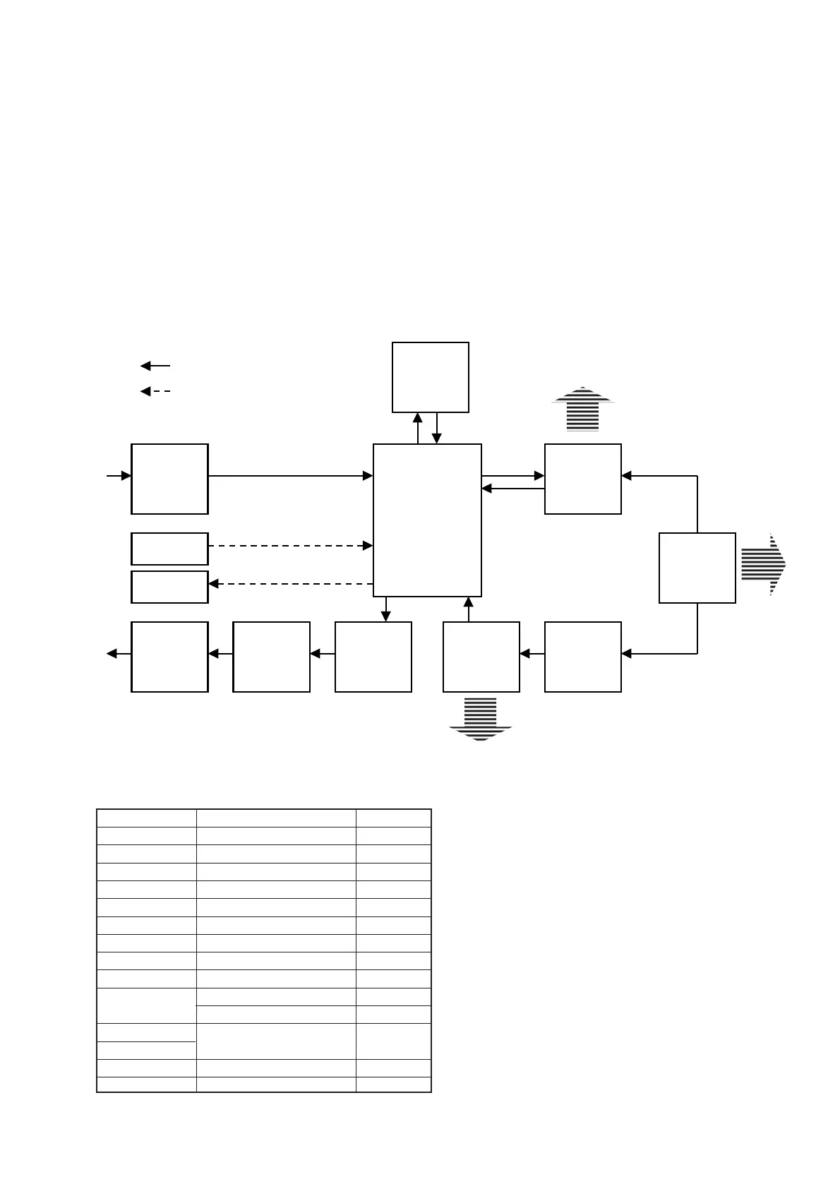
6-1. Device relation diagram.
Display data (for your reference to check the signal path)
VIDEO
ENCODER
IP
CONVERTER
TL750
VIDEO
DECODER
GT R
FBI
AV
DECODER
MSP
Data read
AV
ENCODER
Data read
DV
ADC
DAC
Data rea
Audio signal
Video signal
All parts are mounted on the RD045M’T assembly.
Checking item IC name REF
VIDEO ENC IC ADV7300AKST IC2303
IP CONV IC CXD9698R IC2301
TL750 IC TL750B5 IC1402
GTR IC CXD9735Q IC701
FBI IC CXD9537AR IC1301
VIDEO DEC IC SAA7118E/V1.518 IC2202
AVENC IC UPD61052GD-LML IC903
MSP IC CXD9736GG IC1101
AVDEC IC CXD1935Q IC1203
DV
IC UPD72852GB-8EU IC2001
IC UPD72893GD-LML IC2102
CPRM
IC CXD9754R IC1001
CCM
EPGSLICER IC TC90A73U IC1802
GEMSTAR IC UPD65881GB-072-8ES IC1807
If NG is displayed as the result of DEVICE test, IC is defective or
peripheral of the IC is defective.
If NG is displayed as the result of “PATH” test, defect exists in
between ICs.
 Loading...