Home
Sony
DVD Recorder
RDR GX7
Sony RDR GX7 Service Manual
5
of 1
of 1 rating
97 pages
Give review
Manual
Specs
To Next Page
To Next Page
To Previous Page
To Previous Page
Loading...
RDR-GX7
4-1
4-2
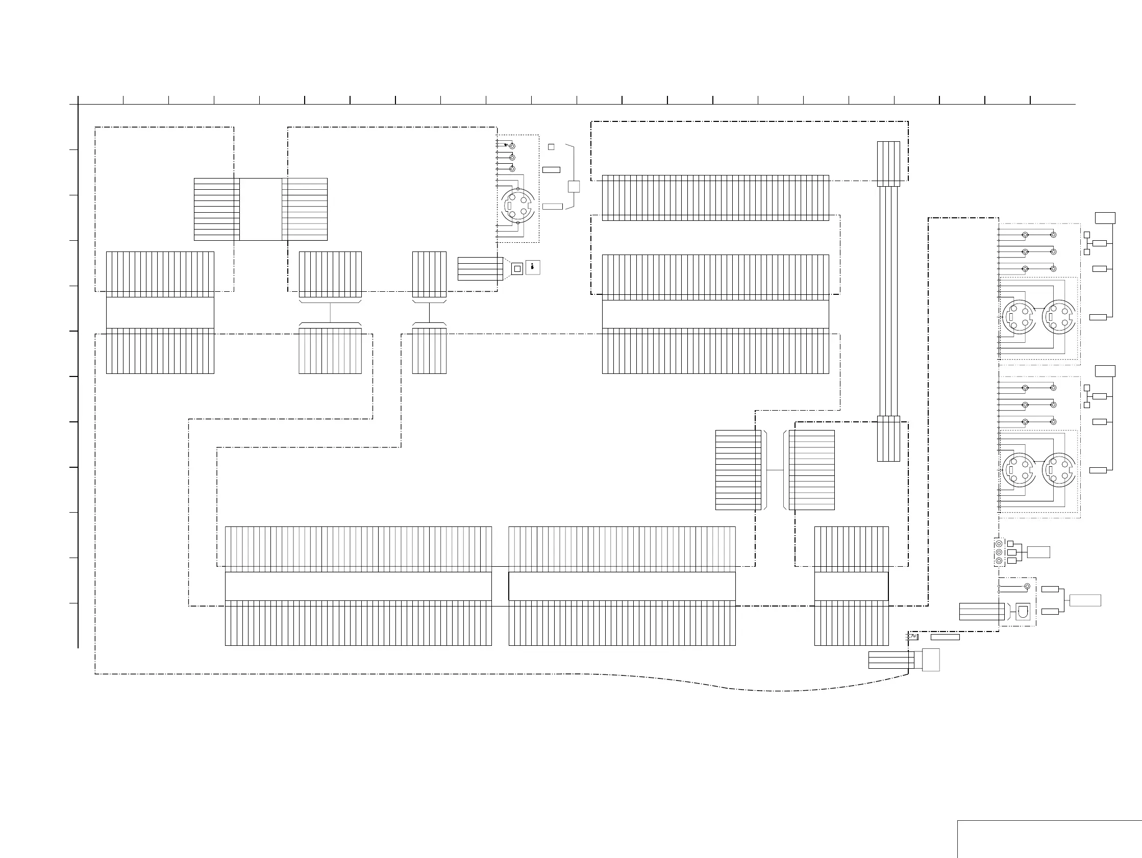
SECTION 4
PRINTED
WIRING BO
ARDS AND SCHEMA
TIC DIA
GRAMS
4-1.
FRAME SCHEMA
TIC DIA
GRAM
FRAME SCHEMA
TIC DIA
GRAM
CN4
1
UNSW6V
2
AGND
3
AGND
4
UNSW3.3V
5
UNSW3.3V
6
UNSW3.3V
7
DGND
8
DGND
9
SW3.3V
10
SW3.3V
11
SW3.3V
12
DGND
13
DGND
14
P_CONT
CN3
1
2
3
4
5
6
7
8
9
10
11
12
13
1
12V
2
GND
3
GND
4
5V
1
12V
2G
N
D
3G
N
D
45
V
CN1705
11P
S2 SW
1
Y2 IN
2
AN GND
3
C2 IN
4
AN GND
5
V2 IN
6
AN GND
7
L2 IN
8
AU GND
9
R2 IN
10
AU GND
11
CN1801
1
2
3
4
5
6
7
8
9
10
11
12
13
14
15
16
17
18
19
20
21
22
23
24
25
26
27
28
29
30
31
32
33
34
35
36
37
38
39
40
40P
CN1802
1
2
3
4
5
6
7
8
9
10
11
12
13
14
15
16
17
18
19
20
21
22
23
24
25
26
27
28
29
30
31
32
33
34
35
36
37
38
39
40
CN1103
40P
GND
1
DASP
2
IDE_A3(CS1)
3
IDE_A4(CS0)
4
IDE_A2
5
IDE_A0
6
NC
7
IDE_A1
8
IDE_HD16
9
IDE_INT
10
GND
11
IDE_DACK
12
NC
13
IDE_IORDY
14
GND
15
IDE_R
16
GND
17
IDE_W
18
GND
19
IDE_DREQ
20
NC
21
GND
22
IDE_D15
23
IDE_D0
24
IDE_14
25
IDE_D1
26
IDE_D13
27
IDE_D2
28
IDE_D12
29
IDE_D3
30
IDE_D11
31
IDE_D4
32
IDE_D10
33
IDE_D5
34
IDE_D9
35
IDE_D6
36
IDE_D8
37
IDE_D7
38
GND
39
IDE_RST
40
14P
CN1701
1
UNSW6V
2
AGND
3
AGND
4
UNSW3.3V
5
UNSW3.3V
6
UNSW3.3V
7
DGND
8
DGND
9
SW3.3V
10
SW3.3V
11
SW3.3V
12
DGND
13
DGND
14
P_CONT
CN1901
47P
1
2
3
4
5
6
7
8
9
10
11
12
13
14
15
16
17
18
19
20
21
22
23
24
25
26
27
28
29
30
31
32
33
34
35
36
37
38
39
40
41
42
43
44
45
46
47
CN1902
40P
1
2
3
4
5
6
7
8
9
10
11
12
13
14
15
16
17
18
19
20
21
22
23
24
25
26
27
28
29
30
31
32
33
34
35
36
37
38
39
40
6P
CN2001
1
GND
2
TPB-
3
TPB+
4
TPA-
5
TPA+
6
GND
CN801
11P
S2 SW
1
Y2 IN
2
AN GND
3
C2 IN
4
AN GND
5
V2 IN
6
AN GND
7
L2 IN
8
AU GND
9
R2 IN
10
AU GND
11
11P
CN1702
1
2
3
4
5
6
7
8
9
10
11
11P
CN102
1
2
3
4
5
6
7
8
9
10
11
19P
CN101
1
2
3
4
5
6
7
8
9
10
11
12
13
14
15
16
17
18
19
19P
CN602
1
2
3
4
5
6
7
8
9
10
11
12
13
14
15
16
17
18
19
40P
CN1202
1
2
3
4
5
6
7
8
9
10
11
12
13
14
15
16
17
18
19
20
21
22
23
24
25
26
27
28
29
30
31
32
33
34
35
36
37
38
39
40
47P
CN1201
1
2
3
4
5
6
7
8
9
10
11
12
13
14
15
16
17
18
19
20
21
22
23
24
25
26
27
28
29
30
31
32
33
34
35
36
37
38
39
40
41
42
43
44
45
46
47
CN1704
6P
DGND
1
TPB-
2
TPB+
3
TPA-
4
TPA+
5
DGND
6
CN101
13P
1
2
3
4
5
6
7
8
9
10
11
12
13
YC
G
G
J1701
1
2
3
4
5
6
7
8
9
10
11
12
13
14
15
16
17
18
19
20
21
22
23
24
25
26
27
28
29
30
31
32
33
34
35
36
37
38
39
40
CN703
1
TPB-
2
TPB+
3
TPA-
4
TPA+
CN301
1
D IN
2
VCC
3
GND
Y
C
G
G
G
Y
C
G
J802
Y
C
G
G
G
Y
C
G
J801
J601
3P
CN102
1
FAN 12V
2
SENS
3
GND
1
A
RD-045 BOARD
BASE UNIT
FR-195 BOARD
FL-130 BOARD
S VIDEO
R
L(MONO)
VIDEO
IDE_D12
IDE_D2
IDE_A1
IDE_D6
IDE_IORDY
IDE_D3
GND
IDE_D7
IDE_DREQ
IDE_D9
IDE_A4(CS1)
IDE_R
DASP
IDE_D15
IDE_INT
GND
IDE_DACK
IDE_HD16
IDE_D13
IDE_A4(CS0)
IDE_D4
IDE_D11
GND
IDE_D14
N.C
IDE_D1
N.C
IDE_D8
GND
IDE_RST
IDE_A0
GND
GND
N.C
IDE_W
IDE_D5
IDE_A2
IDE_D10
GND
IDE_D0
IDE_A0
N.C
IDE_D0
IDE_D2
IDE_D14
IDE_IORDY
GND
IDE_D6
GND
GND
IDE_A4(CS0)
IDE_D7
N.C
IDE_R
IDE_RST
IDE_D9
DASP
IDE_HD16
N.C
GND
IDE_D10
IDE_D8
IDE_A4(CS1)
GND
IDE_A1
IDE_D4
GND
GND
IDE_A2
IDE_D5
IDE_DACK
IDE_D11
IDE_D1
IDE_D3
IDE_D15
IDE_D13
IDE_INT
IDE_W
IDE_D12
IDE_DREQ
CN-177 BOARD
DGND
AGND
B31
AI_BCK
DGND
FY33
EPG_PCONT
SPDIFO
IT_SCLK
AGND
AGND
XITFLMRST
CVBSS
IT_XAWAKE
DGND
SHAWAKE5
DGND
DGND
SPDIFI
AGND
AGND
IT_SIN
RECC
R41
IT_XRST
256FS
AI_SDT
DGND
RECY
G21
SHSTA
TUS1
IT_REQ
AGND
AAD_XRST
AGND
EPGGND
IT_SOUT
FSW
512FS
AGND
DGND
AI_LRCK
AGND
SHSTA
TUS0
AAD_XSCS
EPGVIDEO
FC43
POWER BLOCK
GND
5V
FLD RESET
GND
FLD SOUT
VFL1
FLD CS
+F
KEY4
FLD SCLK
-F
FLD SCLK
VFL
FLD CS
5V
FLD RESET
GND
+F
GND
-F
KEY4
FLD SOUT
DIMMER
KEY4
GND
SIRCS
KEY1
FLD DAT
A
KEY3
-F
FLD RESET
LED STB
KEY2
VFL
FLD CS
GND
5V
GND
KEY5
+F
FLD CLK
GND
5V
KEY1
+F
GND
KEY5
-F
DIMMER
FLD CLK
KEY3
GND
FLD CS
FLD LCK
SIRCS
KEY4
FLD RESET
FLD DAT
A
KEY2
VFL
RECC
SPDIFO
DGND
AI_SDT
AAD_XRST
IT_SIN
AGND
AAD_XSCS
SPDIFI
CVBSS
EPG_PCONT
G21
AGND
EPGGND
AGND
IT_XAWAKE
AGND
R41
XITFLMRST
DGND
EPGVIDEO
SHAWAKE5
RECY
IT_REQ
AGND
DGND
DGND
SHSTA
TUS1
FY33
AGND
AGND
IT_SOUT
256FS
AGND
DGND
AI_LRCK
512FS
FC43
B31
IT_SCLK
AI_BCK
AGND
IT_XRST
DGND
DGND
FSW
SHSTA
TUS0
UNSW13V
N.C
UNSW6V
FAN12V
AGND
UNSW-10V
AC_CONT
DGND
AGND
UNSW18V
DGND
SW3.3V
UNSW6V
UNSW6V
SW3.3V
DGND
UNSW18V
AGND
DGND
AC_CONT
UNSW-10V
AGND
FAN12V
UNSW6V
N.C
UNSW13V
V
ADA_SCK
ADA_XSCS
AO_SDT
DGND
AGND
RS_XEN
C
AGND
XAMUTE
RESERVED
AV_XRST
AGND
AO_LRCK
CB/B
AGND
TEMP
AO_BCK
DGND
RESERVED
ADA_SIN
DGND
DGND
SH_TXD2
Y
TTXT_ENABLE
DIAG
CR/R
XVMUTE
DGND
AGND
Y/G
TTXT_SDA
AGND
ADA_FS96
RESERVED
TTXT_SCL
DGND
SH_RXD2
AGND
C
DIAG
CR/R
DGND
RESERVED
AGND
RESERVED
RS_XEN
ADA_SIN
DGND
DGND
AGND
AO_SDT
CB/B
AGND
SH_TXD2
TTXT_SDA
TEMP
DGND
AO_LRCK
AGND
RESERVED
ADA_XSCS
V
AV_XRST
ADA_SCK
TTXT_SCL
Y
DGND
AGND
XAMUTE
ADA_FS96
XVMUTE
AGND
AGND
AO_BCK
SH_RXD2
Y/G
TTXT_ENABLE
DGND
FLA
T CABLE
FLA
T CABLE
HARNESS
HARNESS
HARNESS
RP-118
DP-090
HARNESS
FRD-002
FRA-002
FRA-003
B to B
DV IN
LINE
2 IN
RF-133
AL-066
FFF-018
F
AR-003
FLA
T CABLE
FLA
T CABLE
FLA
T CABLE
16
J805
COAXIAL
DIGITAL OUT
PCM/DST/
DOLBY DIGITAL
COMPONENT
VIDEO OUT
PR
OPTICAL
PB
Y
FAN
A
V-071 BOARD
20
81
0
1
3
21
7
D
19
14
4
17
6
3
L
E
C
F
11
B
12
K
9
J
18
2
22
5
15
16
G
H
I
R
L
AUDIO
VIDEO
S VIDEO
LINE OUT
2/1
L
AUDIO
VIDEO
S VIDEO
R
LINE OUT
3/1
CONTROL S IN
44
46
Table of Contents
Default Chapter
1
DVD Recorder
1
Specifications
1
Table of Contents
3
Service Note
5
Disk Removal Procedure if the Tray Cannot be Ejected (Forced Ejection)
5
General
7
Features
7
About this Manual
7
DVD Recorder Basics
7
Guide to Parts and Controls
8
Basic Hookups and Settings
9
Quick Overview
9
Step 1: Unpacking
9
Step 2: Connecting the Antenna Cable
9
Step 3: Connecting the Video Cords
10
Step 4: Connecting the Audio Cords
10
Step 5: Connecting the Power Cord
11
Step 6: Preparing the Remote
11
Step 7: Easy Setup
11
Setting up the VCR Plus ® System
11
Setting up the Remote
12
Connecting a VCR or Similar Recording Device to the LINE
12
Jacks
12
Connecting to a Satellite Receiver or a Cable Box
13
Operating the Recorder
13
Guide to Displays
13
How to Use the Displays
13
How to Enter Characters
14
Before Recording
14
Recording TV Programs
15
Timer Recording
15
Adjusting the Recording Picture Quality and Size
17
Recording from External Equipment with a Timer
17
(Synchro Rec)
17
Playback
17
Before Playing
17
Playing Discs
18
Selecting a Recorded Title on a Disc
18
Searching for a Title/Chapter/Track
19
Checking the Play Information and Playing Time
19
Selecting the Sound
19
TV Virtual Surround Settings (TVS)
20
Changing the Angles
20
Displaying the Subtitles
20
Adjusting the Playback Picture and Sound
20
Editing a DVD
21
Before Editing
21
Basic Editing
21
Advanced Editing (Playlist Edit)
22
Labeling, Protecting, or Finalizing the Disc
23
Before Recording/Editing
24
Available DV Dubbing Functions
24
Recording an Entire DV/Digital8 Format Tape
24
One Touch Dub
24
Program Edit
25
Advanced Program Edit
25
Re-Editing the "Program" in the DV/D8 Edit List
26
Creating a Copy of the Edited Contents (Copy Dubbing)
27
Recording from Equipment Connected to the LINE in
27
Jacks
27
Settings and Adjustments
28
About the Setup Display Structure
28
Using the Setup Displays
28
Settings (Basic Settings)
28
Video Settings
29
Audio Settings
29
Features Settings
29
Options Settings
30
Easy Setup (Resetting the Recorder)
30
Additional Information
30
Troubleshooting
30
Self-Diagnosis Function
31
Display
31
Glossary
32
Language Code List
32
Disassembly
33
Disassembly Section
33
2 Disassembly
34
Top Case
34
Power Block
34
Fan
35
Rear Panel
35
Tray Cover Assembly
36
Front Panel Section
36
DVD Drive
40
Board
41
Circuit Boards Location
42
Block Diagrams
43
Overall Block Diagram (1/2)
43
Overall Block Diagram (2/2)
44
Printed Wiring Boards and Schematic Diagrams
45
Frame Schematic Diagram
45
Printed Wiring Boards and
46
Waveforms
46
Vhf/Uhf Tuner
47
Video in Process
48
Rd I/F)(3/9) Schematic Diagram
49
A/V In/Out Terminal
50
5 IC Pin Function Description
51
Audio in
51
Av-071 Board
51
Service Mode
65
Device Relation Diagram
65
Display Data (for Your Reference to Check the Signal Path)
65
Block Diagram
66
(For Your Reference to Check the Devices)
66
Screen Transition in the Service Mode
66
Service Mode. Menu Items and Description
67
Device Check Menu (1/2)
67
Device Check Menu (2/2)
67
Path Check Menu (1/2)
68
Path Check Menu (2/2)
68
Device All Check. Screen Transition
69
Device Individual Check. Screen Transition
69
Path Individual Check (Pasted Screen Check)
70
Screen Transition
70
Path Individual Check (Data Check Confirmation)
70
Adjustment
71
Video System Adjustment
71
Video Level Adjustment (RD-045 Board)
71
Component Video Output Level Adjustment
71
(RD-045 Board)
71
S-Video Output S-Y Level Check
71
S-Video Output S-C Check
71
Component Video Output y Check
72
Component Video Output B-Y Check
72
Component Video Output R-Y Check
72
Repair Parts List
73
Exploded Views
73
Overall
73
Front Panel Section
74
Chassis Section
75
Electrical Parts List
76
Other manuals for Sony RDR GX7
Operating Instructions
112 pages
Quick Start Guide
3 pages
Hookups And Settings
28 pages
Technical Notes
34 pages
Supplementary Guide
12 pages
Supplement
4 pages
Frequently Asked Questions
7 pages
5
Based on 1 rating
Ask a question
Give review
Questions and Answers:
Need help?
Do you have a question about the Sony RDR GX7 and is the answer not in the manual?
Ask a question
Sony RDR GX7 Specifications
General
I/O ports
Analog AV In/Out S-Video In/Out Component Video Out DV Terminal (i.LINK) 2 x Scart (1 including RGB in) Digital Audio Out
Related product manuals
Sony RDR-GX3
100 pages
Sony RDR-GX350
112 pages
Sony RDR-GX330
98 pages
Sony RDR-GX300
2 pages
Sony RDR-GX700
116 pages
Sony RDR-GX310
112 pages
Sony RDR-GX360
128 pages
Sony RDR-GX257
84 pages
Sony RDR-GX380
92 pages
Sony RDR-GX210
96 pages
Sony RDR-GXD455
83 pages
Sony RDR- RDR-GX355
82 pages
 Loading...