RDR-GX7
4-44-3
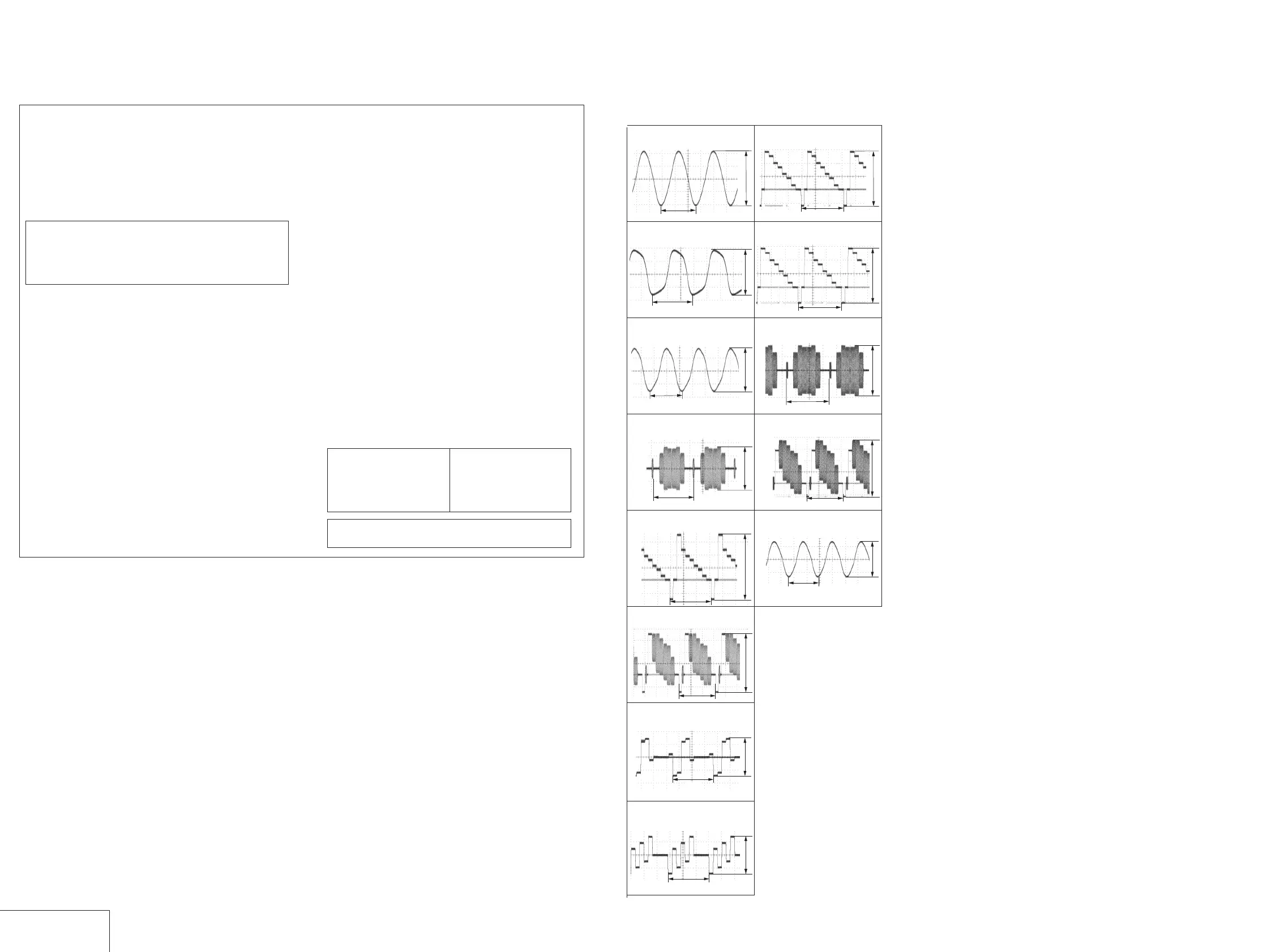
WAVEFORMS
AV-071
(For printed wiring boards)
• X : indicates a lead wire mounted on the component side.
• x : indicates a lead wire mounted on the printed side.
• a : Through hole.
• b : Pattern from the side which enables seeing.
(The other layers' patterns are not indicated.)
THIS NOTE IS COMMON FOR WIRING BOARDS AND SCHEMATIC DIAGRAMS
(In addition to this, the necessary note is printed in each block)
When indicating parts by reference number, please include
the board name.
Caution:
Pattern face side: Parts on the pattern face side seen from
(Side B) the pattern face are indicated.
Parts face side: Parts on the parts face side seen from
(Side A) the parts face are indicated.
(For schematic diagrams)
• All capacitors are in µF unless otherwise noted. pF : µµF.
50V or less are not indicated except for electrolytics and
tantalums.
• All resistors are in ohms, 1/4 W (Chip resistors : 1 /10 W) un-less
otherwise specified.
kΩ=1000Ω, MΩ=1000kΩ.
• Caution when replacing chip parts.
New parts must be attached after removal of chip.
Be careful not to heat the minus side of tantalum capacitor, be-
cause it is damaged by the heat.
• All variable and adjustable resistors have characteristic curve B,
unless otherwise noted.
• 2 : non flammable resistor
• 5 : fusible resistor
• C : panel designation
• f : internal component.
• C : adjustment for repair.
• U : B+ Line
• V : B– Line
• Circled numbers refer to waveforms.
• Voltages are dc between measurement point.
• Readings are taken with a color-bar signals on DVD reference
disc.
• Readings are taken with a digital multimeter (DC 10MW).
• Voltage variations may be noted due to normal production toler-
ances.
4-2. PRINTED WIRING BOARDS AND SCHEMATIC DIAGRAMS
Note :
The components identified by
mark 0 or dotted line with mark
0 are critical for safety.
Replace only with part number
specified.
Note :
Les composants identifiés par
une marque 0 sont critiques
pour la sécurité.
Ne les remplacer que par une
pièce portant le numéro spécifié.
54.3ns
30.5µs
50ns
H
AV-071 BOARD
2 IC605 eh
1 IC407 6
3.4Vp-p
4.2Vp-p
3 IC605 ek
3.3Vp-p
4 IC701 qa (S-VIDEO IN)
H
670mVp-p
5 IC701 wa (S-VIDEO IN)
H
1.0Vp-p
6 IC701 ef (VIDEO IN)
1.0Vp-p
7 IC802 w; (PLAY)
H
1.4Vp-p
8 IC802 ws (PLAY)
1.4Vp-p
H
H
H
226ns (PAL)
279ns (NTSC)
q; IC802 wl (PLAY)
9 IC802 wf (PLAY)
2.0Vp-p
2.0Vp-p
qa IC802 ea (PLAY)
1.8Vp-p
qs IC802 ed (PLAY)
H
2.5Vp-p
qd IC1101 es
5.4Vp-p
H
WAVEFORMS
 Loading...