7-1
SECTION 7
ADJUSTMENT
RDR-GX7
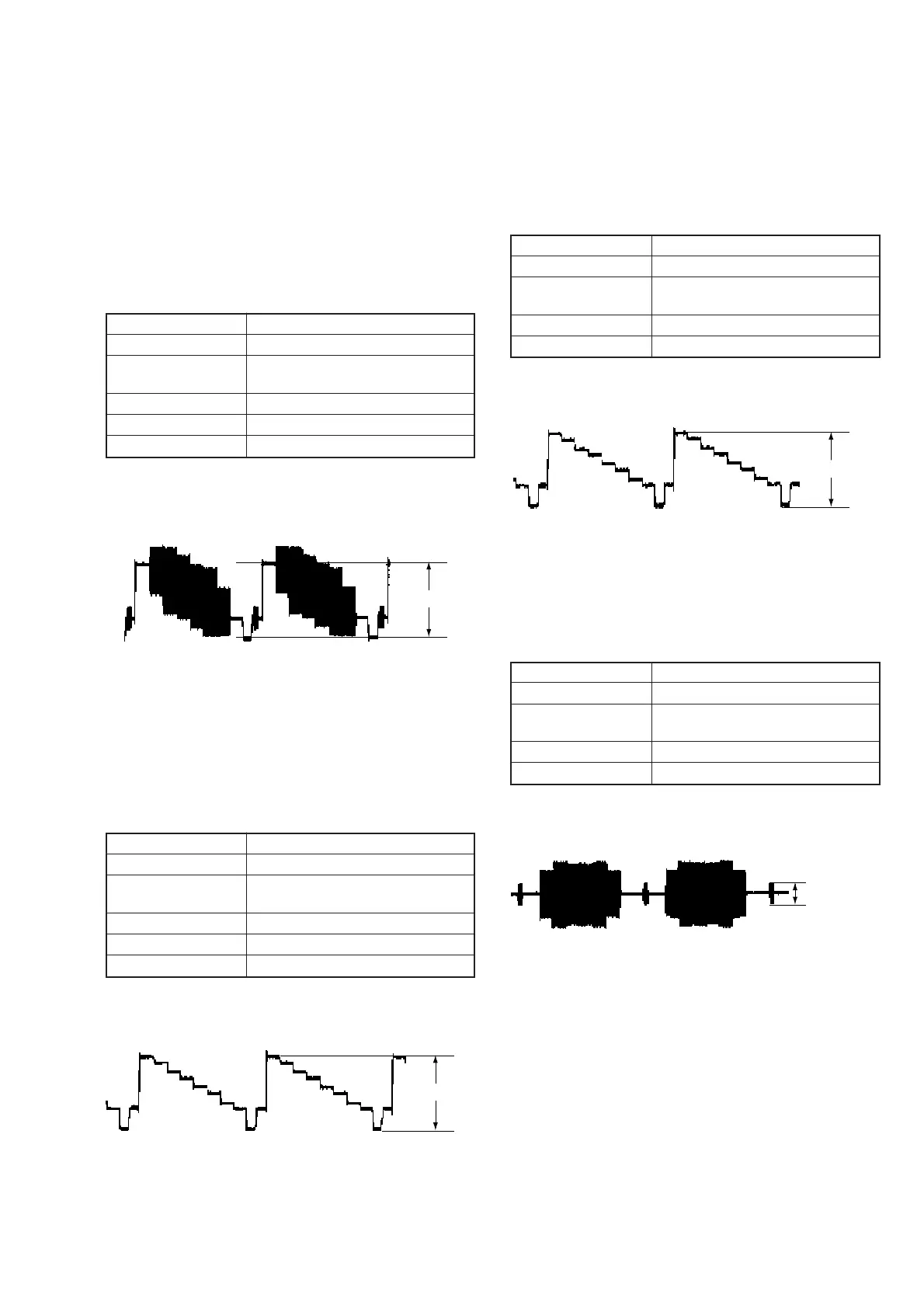
7-1. VIDEO SYSTEM ADJUSTMENT
Reference Disk
HLX-505 (NTSC Single layer disk) J-6090-089-A
HLX-504 (NTSC Dual layer disk) J-6090-088-A
1. Video Level Adjustment (RD-045 Board)
< Purpose >
This adjustment is made to satisfy the NTSC standard. If it is adjusted
incorrectly, brightness will be too bright or too dark.
Mode Video level adjustment in test mode
Signal Colour bars
Test point LINE OUT (VIDEO) connector
(terminated in 75Ω)
Instrument Oscilloscope
Adjusting element RV2301
Specification 1.00 Vp-p
Adjusting method:
1 ) Insert the reference disk and play back the 100% colour bars.
2 ) Adjust RV2301 for 1.0 Vp-p.
Fig. 7-1
2. Component Video Output Level Adjustment
(RD-045 board)
< Purpose >
This is the adjustment for component video output. If this adjustment
is made incorrectly, brightness of the component signal that is
connected to the projector having COMPONENT input will have
incorrect brightness.
Mode Video level adjustment in test mode
Signal Colour bars
Test point COMPONENT VIDEO OUT (Y)
connector (terminated in 75Ω)
Instrument Oscilloscope
Adjusting element RV2302
Specification 1.00 Vp-p
Adjusting method:
1 ) Insert the reference disk and play back the 100% colour bars.
2 ) Check that the Y level is 1.00 Vp-p.
1.0 Vp-p
+ 0.04
– 0.02
Fig. 7-2
1.0 Vp-p
+ 0.04
– 0.02
3. S-Video Output S-Y Level Check
< Purpose >
This check confirms that the video output level at the S-video output
connector is correct. If this adjustment is made incorrectly, picture
will not be displayed correctly when the S-video connector output
signal is connected to TV using cable.
Mode Video level adjustment in test mode
Signal Colour bars
Test point S-VIDEO OUT (S-Y) connector
(terminated in 75Ω)
Instrument Oscilloscope
Specification 1.0 ± 0.05Vp-p
Adjusting method:
1 ) Insert the reference disk and play back the 100% colour bars.
2 ) Check that the S-Y level is 1.0 ± 0.05 Vp-p.
Fig. 7-3
4. S-Video Output S-C Check
< Purpose >
This check confirms that the S-video output S-C conforms to the
NTSC standard. If it is adjusted incorrectly, colour will be too dark
or too thin.
Mode Video level adjustment in test mode
Signal Colour bars
Test point S-VIDEO OUT (S-C) connector
(terminated in 75Ω)
Instrument Oscilloscope
Specification 286 ± 30mVp-p
Checking method:
1 ) Insert the reference disk and play back the 100% colour bars.
2 ) Confirm that the burst signal level of S-C is 300 ± 30mVp-p.
1.0
±
0.05 Vp-p
Fig. 7-4
286
±
30 mVp-p
+ 0.04
– 0.02
+ 0.04
– 0.02
+ 0.04
– 0.02
 Loading...