7-2E
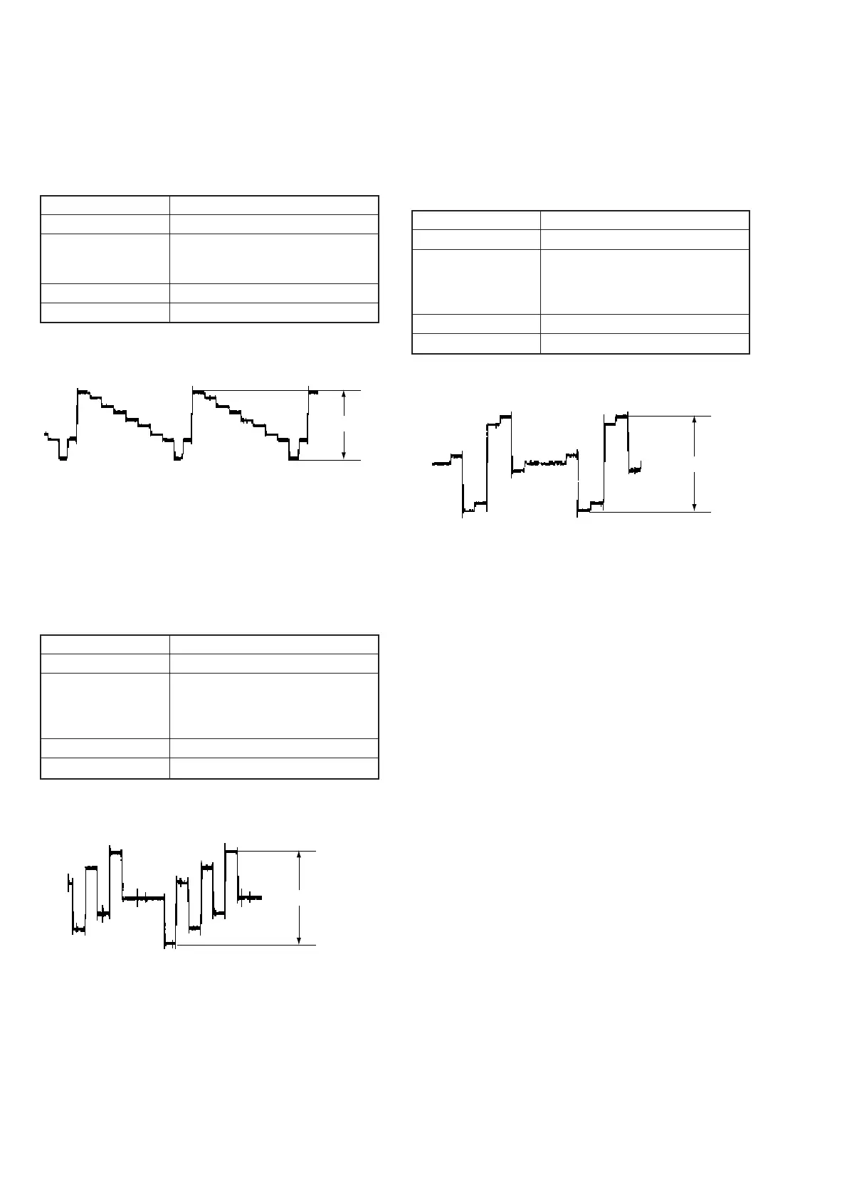
5. Component Video Output Y Check
< Purpose >
This check confirms that the Y signal output is correct. If this signal
level is not correct, brightness of video signal will be too bright or
too dark when the COMPONENT connector output signal is
connected the projector having COMPONENT input.
Mode Video level adjustment in test mode
Signal Colour bars
Test point
COMPONENT VIDEO OUT (Y) connector,
D1/D2 VIDEO OUT connector, pin-1
(terminated in 75Ω)
Instrument Oscilloscope
Specification 1.0 ± 0.05 Vp-p
Checking method:
1 ) Insert the reference disk and play back the 100% colour bars.
2 ) Check that the Y level is 1.0 ± 0.05 Vp-p.
Fig. 7-5
6. Component Video Output B-Y Check
< Purpose >
This check confirms that the B-Y signal of the component video
output is correct. If this signal level is not correct, colour of the
video signal will have different colour when the COMPONENT
connector output signal is connected the projector having
COMPONENT input.
Mode Video level adjustment in test mode
Signal Colour bars
Test point COMPONENT VIDEO OUT (PB/CB)
connector,
D1/D2 VIDEO OUT connector,
pin-3 (terminated in 75Ω)
Instrument Oscilloscope
Specification 700 ± 50 mVp-p
Checking method:
1 ) Insert the reference disk and play back the 100% colour bars.
2 ) Confirm that the B-Y level is 700 ± 50 mVp-p.
1.0
±
0.05 Vp-p
Fig. 7-6
7. Component Video Output R-Y Check
< Purpose >
This check confirms that the R-Y signal of the component video
output is correct. If this signal level is not correct, colour of the
video signal will have different colour when the COMPONENT
connector output signal is connected the projector having
COMPONENT input.
Mode Video level adjustment in test mode
Signal Colour bars
Test point COMPONENT VIDEO OUT (PR/CR)
connector,
D1/D2 VIDEO OUT connector,
pin-5 (terminated in 75Ω)
Instrument Oscilloscope
Specification 700 ± 50 mVp-p
Checking method:
1 ) Insert the reference disk and play back the 100% colour bars.
2 ) Confirm that the R-Y level is 700 ± 50 mVp-p.
700
±
50 mVp-p
Fig. 7-7
700
±
50 mVp-p
 Loading...