1-8 (E)
VPL-HW40ES
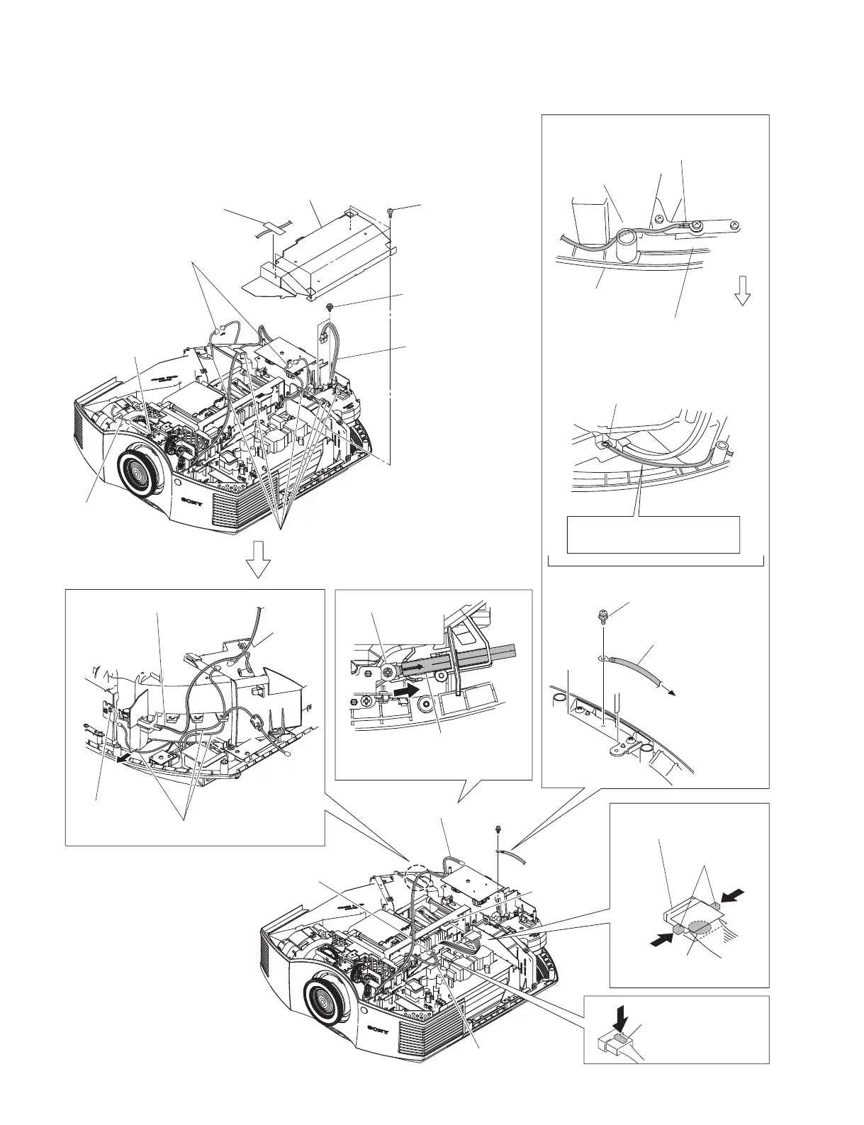
Remove it while
pressing the hook
of the connector.
Hook
2 Four screws
(PSW3 x 8)
!= Three harnesses
Fuse connector assembly
!- Remove the fuse connector
assembly in the direction of the
arrow.
Fuse connector assembly
!\ Harness
C board
CN1000
C board
CN2000
TL board
CN60
0 Loosen screw.
To the chassis.
8 Screw
(PSW3 x 8)
9 GND wire
harness
When installing the GND wire harness,
insert the GND wire harness in between
the optical unit and the bottom cover
assembly.
The lug terminal should not
protrude exceeding the chassis.
Bottom cover
assembly
Optical unit
Front side
Pull the GND harness front to
give tension.
Chassis
4 Two screws
(BVWHTP3 x 12)
5 Lamp power
connector assembly
Harness
HB board
CN20
7 Two fan connectors
6 Six hooks
![ Press the
two hooks.
Marking is printed on the
bottom.
!] Lead with connector
(LVDS)
3 Shield (PW)
1 Ta p e
1-3-6. C Board-1
t When removing the C board, perform the procedure in Sections
1-3-6 to 1-3-8.