1-18 (E)
VPL-HW40ES
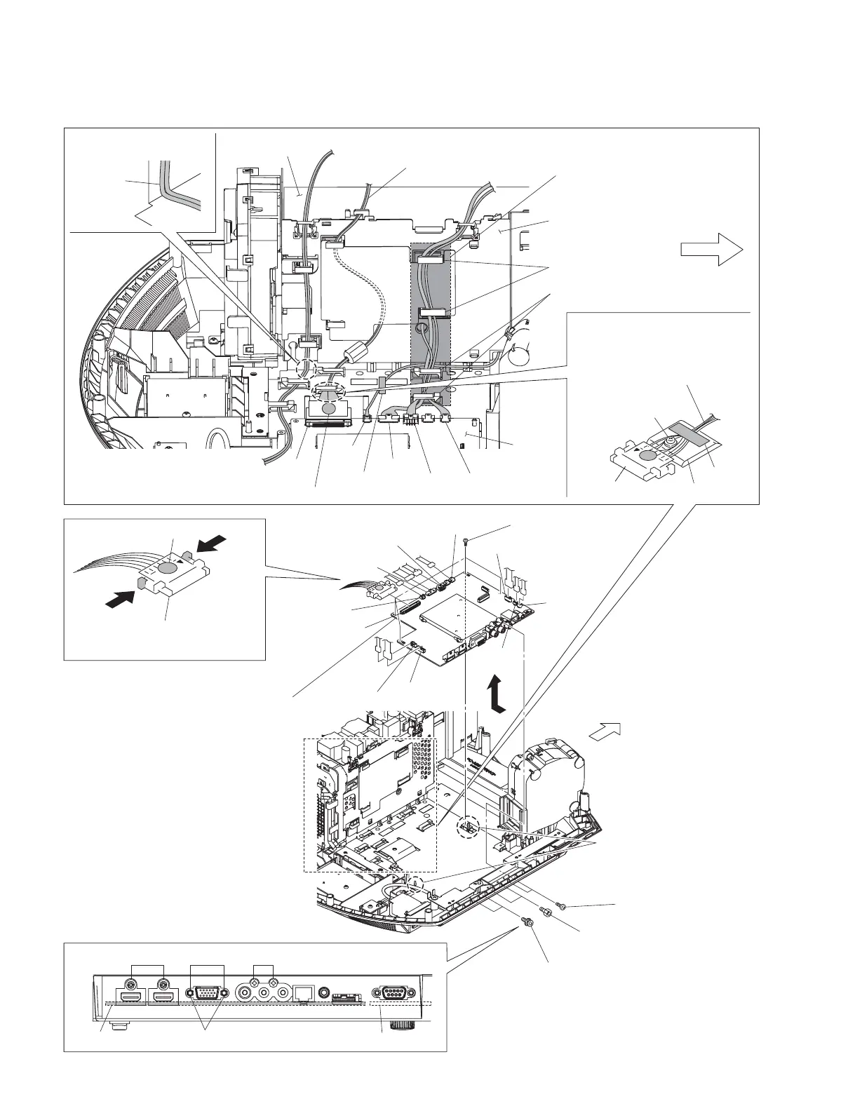
1-3-17. QA Board
Marking is printed on the top.
Lead wire with connector
(LVDS)
1 Four screws
(PSW3 x 8)
2 Two screws
(BVTP3 x 12)
3 Two SP4-40 UNC screws
(No height difference)
4 Two screws
(PSW3 x 8)
5 Two dowels
6 Remove the QA board
in the direction of the
arrow D.
CN701
CN800
CN602
CN703
CN801
CN600
CN301
CN702
CN400
CN1001
Front side
D
QA board
Two SP4-40 UNC screws (No height difference)
QB board
432
CN301
Tape
Chassis
Harness of the lead with connector
(LVDS) should not override on top
of the chassis screw.
Chassis screw
Lead with connector
(LVDS)
Front side
CN301
QA board
GA board
G board holder block
Hooks of plate clamp
Hooks of bottom cover assembly
When installing the harness,
the harness should not protrude
exceeding the shaded area.
Lead wire with connector
(LVDS)
Harness
Place the harness at a right
angle as shown in the figure.
Marking is printed on the top.
Tape
CN400
CN602
CN600
CN1001