Do you have a question about the Sony RM-PJ25 and is the answer not in the manual?
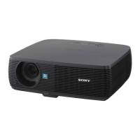
Illustrates the projector's exterior and internal component locations.
Specifies torque values for various screws during disassembly/assembly.
Provides step-by-step instructions and diagrams for disassembling the projector.
Details extension boards and cables for additional connectivity options.
Explains the meaning of ON/STANDBY and LAMP/COVER indicator lights and error codes.
Explains the function of various boards like QA, QB, C, GA, GB, etc.
Provides guidelines for disconnecting and connecting flexible card wires to prevent damage.
Advises on the use of lead-free solder for repairs and soldering iron temperature.
Lists required equipment and initial power-on setup for electrical adjustments.
Instructions on how to access and exit the projector's service mode.
Details procedures for adjusting white balance in D93, D75, D65, D55, and Custom modes.
Explains how to copy panel driver gain B and panel alignment data.
Steps for adjusting panel driver gain B while measuring luminance.
Procedures for upgrading SUB CPU and Scan Converter software.
Explains the organization of memory blocks for storing various settings and data.
Provides data for initializing various adjustment items.
Highlights critical components and standardization of parts for safe replacement.
Displays exploded diagrams of the projector's main assemblies and parts.
Lists electrical components with part numbers and descriptions for the C board.
Lists items included in the package and packing materials.
Shows the main functional blocks and their interconnections within the projector.
Illustrates the detailed block diagram for the QA board, including inputs and outputs.
Presents the block diagram for the C board, detailing its connections and functions.
Shows the block diagram for the GA board, including power supply and AC filter functions.
Illustrates the block diagram for the GB board, detailing the main power supply functions.
Provides detailed circuit schematics for the HA and HB boards.
Displays the detailed circuit schematics for the C board.
Presents the detailed circuit schematics for the QA board.
Shows schematic diagrams for NF, QB, TL, U, and V boards.
Illustrates the component placement and layout for the C board.
Shows the component placement and layout for the GA board.
Displays the component placement and layout for the GB board.
Illustrates the component placement and layout for the QA board.
Shows the component placement and layout for the EM board.
Displays the component placement and layout for the HA board.
Illustrates the component placement and layout for the HB board.
Shows the component placement and layout for the NF board.
Displays the component placement and layout for the QB board.
Illustrates the component placement and layout for the TL board.
Shows the component placement and layout for the U board.
Displays the component placement and layout for the V board.
Details procedures for measuring AC leakage current from exposed metal parts.