– 5 –
1) Remove the case from the set. (Refer to 2-1)
2) Remove the MB-98 board. (Refer to 2-1)
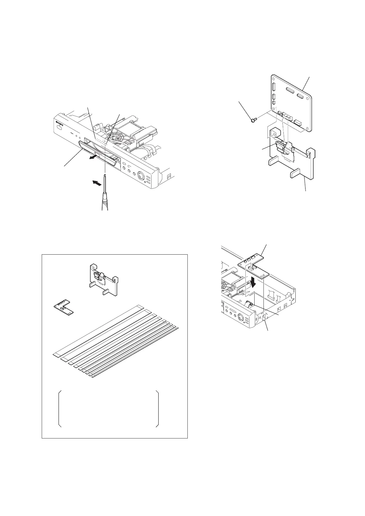
3) Set the stand (with CK-106 board) as shown in Fig. 2.
Fig. 2
4) Set the Jig A board as shown in Fig. 3.
Fig. 3
2. DISC REMOVAL PROCEDURE
(at POWER OFF)
1) Insert a tapering driver into the aperture of the unit bottom,
and move the lever of chuck cam in the direction of the arrow
A. (See Fig. 1)
2) Draw out the tray in the direction of the arrow B, and remove
a disc. (See Fig. 1)
Fig. 1
3. HOW TO SERVICE MB-98 BOARD
• Jig (J-6090-107-A) Extension cable
Tray
Lever of chuck cam
Aperture
B
A
CK-105 board
Stand
(with CK-106 Board)
Nine flexible flat cables
FFC 5P (EXCEPT DVP-NC600), FFC 9P,
FFC 15P, FFC26P,
FFC 9P (DVP-NS500P/NS700P),
FFC 15P (DVP-NS400D),
FFC 25P (EXCEPT DVP-NS300 J model),
FFC 29P (DVP-NS300 J model)
1 MB-98 board
2 Stand
(with CK-106 board)
3 Connector (CN101)
4 Two screws (B3)
4 Connector (CN109)
1 CK-105 board
3 Claw
2