HT-ST9
20
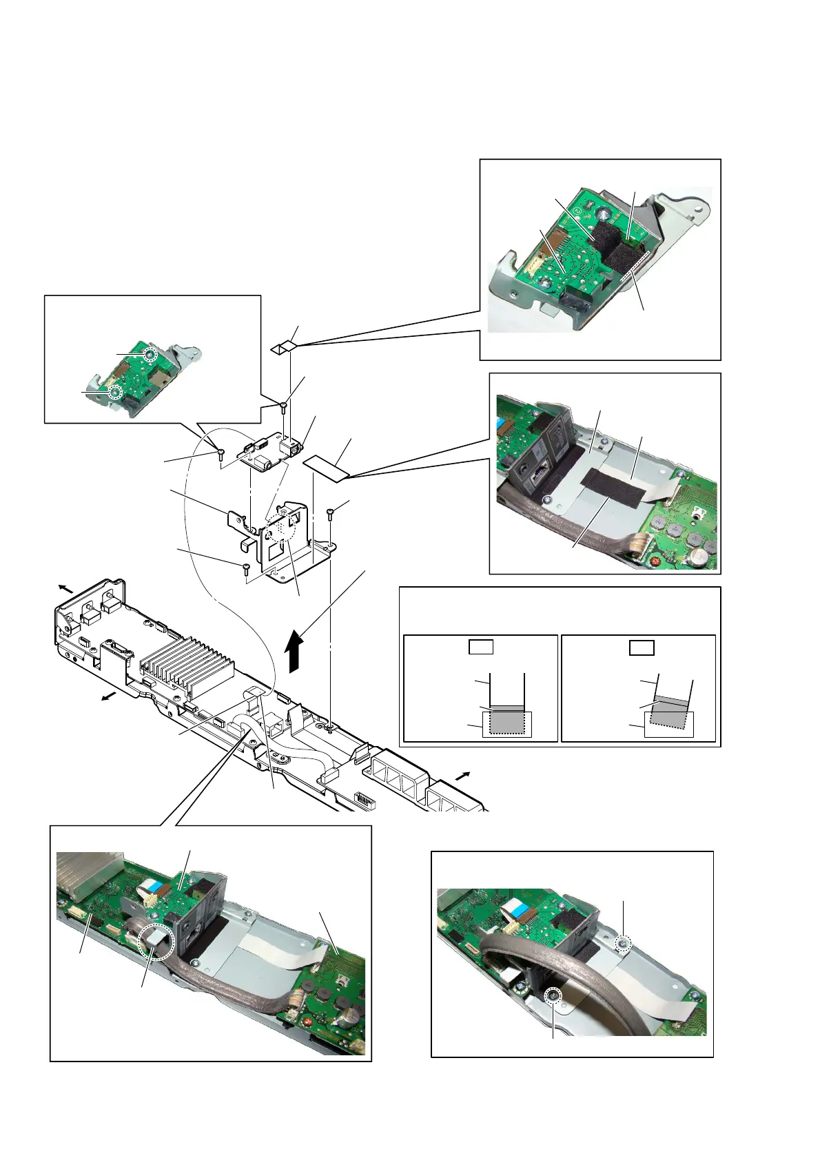
2-11. IO BOARD
colored line
Insert straight into the interior.
flexible flat
cable
connector
OK
colored line
Insert at a slant.
flexible flat
cable
connector
NG
How to install the flexible flat cable
When installing the flexible flat cable, ensure that
the colored line is parallel to the connector after insertion.
:iUe settinJ
– ,O boaUG blocN toS Yiew –
hook
guide line
CN1701
– &hassis blocN UeaU Yiew –
3astinJ Sosition of the cXshion 7
9 IO board
1 cushion (H15)
2 FFC (9P) (FFC2)
(CN1702)
cushion (T05)
cushion (H15)
3 screw
(BVTP3 u 8)
3 screw
(BVTP3 u 8)
4 Remove the IO board
block in the direction
of the arrow.
5 cushion (T05)
6 screw
(BVTP3 u 8)
6 screw
(BVTP3 u 8)
7 hook
8 bracket (I/O) assy
bracket (I/O) assy
3astinJ Sosition of the cXshion H
MB1406
board
IO board
AMP board
FFC (28P) (FFC1)
IO board
Right side
Top side
Bottom side
The lower side is
the terminal side.
Note 1:
When installing screws (BVTP3 × 8),
follow the installing procedure in the
numerical order given.
2
1
1
2
Note 2:
When installing screws (BVTP3 × 8), follow the
installing procedure in the numerical order given.