HT-ST9
28
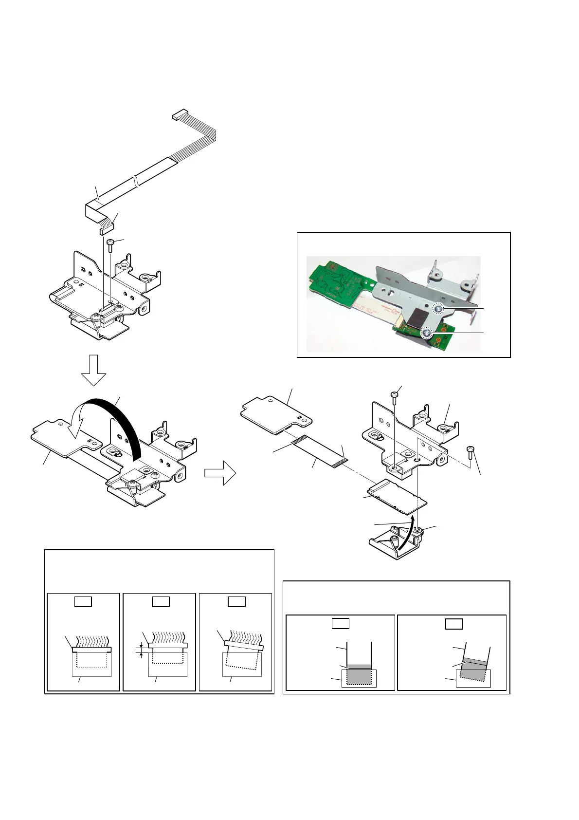
2-19. WS BOARD, RF MODULATOR (RF1)
– RF modulator block rear bottom view –
1 connector
(CN1401)
4 screw
(BVTP3 u 8)
2 screw
(BVTP3 u 8)
4 screw
(BVTP3 u 8)
5 bracket (USB)
assy
7 holder (WS) assy
9 WS board
WS board
8 FFC (26P)
(FFC3)
0 RF modulator
(RF1)
terminal
side
terminal
side
Copper covered side.
Insert only part way.Insert straight into
the interior.
connector
Insert at a slant.
connector
connector
connector
connector connector
OK NG NG
How to install the connector
Insert the connector straight into the interior.
There is a possibility that using this unit without
the connector correctly installed will damage it.
colored line
Insert straight into the interior.
flexible flat
cable
connector
OK
colored line
Insert at a slant.
flexible flat
cable
connector
NG
How to install the flexible flat cable
When installing the flexible flat cable, ensure that
the colored line is parallel to the connector after insertion.
3
Open the
WS
board
in the
direction of the arrow.
6
Remove the
RF modulator block
in the direction of the arrow.
2
1
Note:
When installing screws (BVTP3 × 8), follow the installing
procedure in the numerical order given.