HT-ST9
21
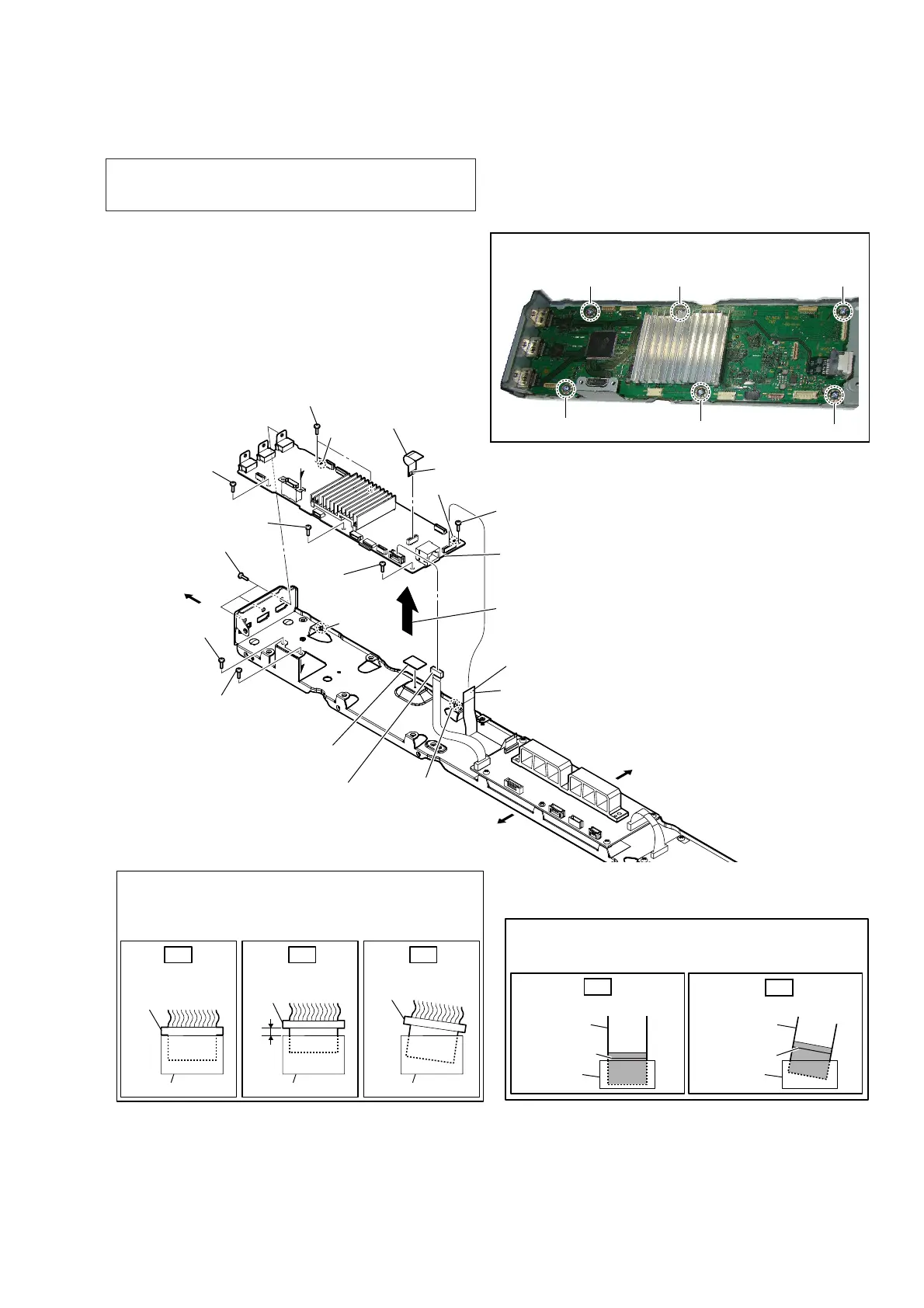
2-12. MB1406 BOARD
Insert only part way.Insert straight into
the interior.
connector
Insert at a slant.
connector
connector
connector
connector connector
OK NG NG
How to install the connector
Insert the connector straight into the interior.
There is a possibility that using this unit without
the connector correctly installed will damage it.
colored line
Insert straight into the interior.
flexible flat
cable
connector
OK
colored line
Insert at a slant.
flexible flat
cable
connector
NG
How to install the flexible flat cable
When installing the flexible flat cable, ensure that
the colored line is parallel to the connector after insertion.
– Chassis block rear view –
3 connector
(CN301)
2 FFC (28P) (FFC1)
(CN703)
5 screw
(BVTP3 u 8)
4 three screws
(B3 u 6)
1 FFC (9P) (FFC2)
(CN701)
terminal side
4 screw
(B3 u 6)
4 screw
(B3 u 6)
5 screw
(BVTP3 u 8)
5 screw
(BVTP3 u 8)
5 screw
(BVTP3 u 8)
5 two screws
(BVTP3 u 8)
Right side
Top side
Bottom side
The lower side is
the terminal side.
guide pin
guide pin
hole
6
Remove the
MB1406
board
in the direction of the arrow.
hole
7 radiation sheet
8 MB1406 board
Note 2:
When installing the MB1406 board, align
the two guide pins and two holes.
Note 3:
When installing screws (BVTP3 × 8), follow the installing
procedure in the numerical order given.
1
2
3
5
4
6
Note 1: When the complete MB1406 board is replaced, refer to
“NOTE OF REPLACING THE COMPLETE MB1406
BOARD OR CARD WLAN/BT COMBO” on page 6.