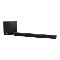
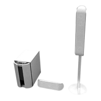
HT-ST9
4
1. SERVICING NOTES ............................................. 5
2. DISASSEMBLY
2-1. Disassembly Flow ........................................................... 10
2-2. Cover (Rear) Block ......................................................... 12
2-3. Rear Panel (L) Block ...................................................... 13
2-4. Rear Panel (R) Assy, Base Cover (Rear) ........................ 14
2-5. KEY Board, Button Assy ................................................ 14
2-6. Panel (Side L, R) ............................................................. 15
2-7. Panel (Bottom) Block ..................................................... 16
2-8. Chassis Block-1 .............................................................. 17
2-9. Chassis Block-2 .............................................................. 18
2-10. AMP Board ..................................................................... 19
2-11. IO Board ......................................................................... 20
2-12. MB1406 Board ............................................................... 21
2-13. Power Cord (AC1) .......................................................... 22
2-14. POWER Board ................................................................ 23
2-15. RF Modulator Block-1 .................................................... 24
2-16. RF Modulator Block-2 .................................................... 25
2-17. RF Modulator Block-3 .................................................... 26
2-18. USB Board ...................................................................... 27
2-19. WS Board, RF Modulator (RF1) .................................... 28
2-20. Card WLAN/BT Combo (WIFI1)................................... 29
2-21. Center Speaker Block ..................................................... 30
2-22. Front Speaker (R) Block ................................................. 31
2-23. Front Speaker (L) Block ................................................. 32
2-24. Grille Assy ...................................................................... 33
2-25. NFC Module (NFC1) ...................................................... 33
2-26. DISPLAY Board Block-1 ............................................... 34
2-27. DISPLAY Board Block-2 ............................................... 35
2-28. DISPLAY Board, OLED Display (OLED1) ................... 36
2-29. Loudspeaker (SP3, SP4) (R-ch)-1 .................................. 37
2-30. Loudspeaker (SP3, SP4) (R-ch)-2 .................................. 38
2-31. Loudspeaker (SP1, SP2) (L-ch)-1 ................................... 39
2-32. Loudspeaker (SP1, SP2) (L-ch)-2 ................................... 40
2-33. Loudspeaker (SP5, SP6, SP7, SP8) (Center) .................. 41
2-34. Loudspeaker (SP9, SP10) (Center)-1 .............................. 42
2-35. Loudspeaker (SP9, SP10) (Center)-2 .............................. 43
2-36. Connection Cable with Speaker (SPC3, SPC4) .............. 44
TABLE OF CONTENTS
3. TEST MODE
............................................................ 45
4. TROUBLESHOOTING .......................................... 53
5. DIAGRAMS
5-1. Block Diagram - HDMI Section - ................................... 57
5-2. Block Diagram - MEMORY/MAIN Section - ................ 58
5-3. Block Diagram - AMP Section - ..................................... 59
5-4. Block Diagram
- PANEL/POWER SUPPLY Section - ............................ 60
5-5. Printed Wiring Board - MB1406 Board - ....................... 62
5-6. Printed Wiring Board - AMP Board - ............................. 63
5-7. Schematic Diagram - AMP Section (1/2) - ..................... 64
5-8. Schematic Diagram - AMP Section (2/2) - ..................... 65
5-9. Printed Wiring Boards - IO/USB Section - ..................... 66
5-10. Schematic Diagram - IO/USB Section - ......................... 66
5-11. Printed Wiring Board - WS Board - ................................ 67
5-12. Schematic Diagram - WIRELESS Section - ................... 67
5-13. Printed Wiring Boards - DISPLAY Section - ................. 68
5-14. Schematic Diagram - DISPLAY Section - ...................... 69
5-15. Printed Wiring Board - POWER Board - ........................ 70
5-16. Schematic Diagram - POWER Board - .......................... 71
6. EXPLODED VIEWS
6-1. Rear Panel Section .......................................................... 73
6-2. Side Panel Section .......................................................... 74
6-3. Chassis Section ............................................................... 75
6-4. Front Block Section ........................................................ 76
6-5. Center Speaker Section ................................................... 77
6-6. Speaker (L-ch) Section ................................................... 78
6-7. DISPLAY Board Section ................................................ 79
6-8. Speaker (R-ch) Section ................................................... 80
6-9. Front Panel Section ......................................................... 81
7. ELECTRICAL PARTS LIST .............................. 82
Accessories are given in the last of the electrical parts list.