74
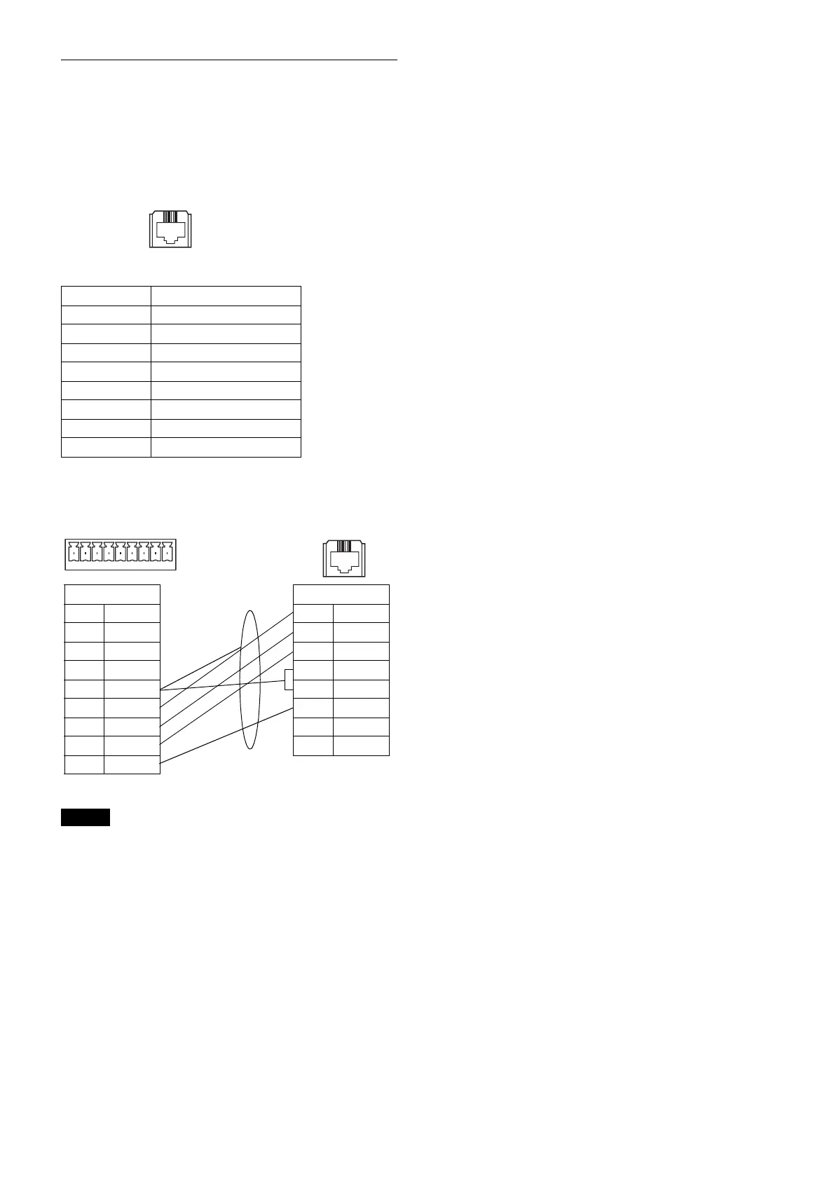
Using the VISCA RS-422 connector
pin assignments
The VISCA RS-422 connector pin
assignments
Connection diagram of a Remote Control
unit (RM-IP10)
• In order to stabilize the voltage level of the signal,
connect both ends to GND.
• For the network cable, use a cable that is category 5e or
higher and is equivalent or higher than a shield twist
pair.
Pin No. Function
1TX –
2TX +
3RX –
4GND
5GND
6RX +
7
8
Notes
1 8
19
RM-IP10
1
2
3
4
5GND
6RX –
7RX +
8TX –
9TX +
SRG-360SHE
1TX –
2TX +
3RX –
4GND
5GND
6RX +
7
8
1 8
Shield
 Loading...