9
n Screw hole for HDMI cable fixing plate
Mount the supplied “HDMI cable fixing plate”.
o SDI OUT connector
Outputs video from this product as an HD SDI (3G-
HD SDI compatible) video signal.
p LAN connector (RJ-45 8-pin)
Network communication and PoE+* power supply are
performed by using the network cable (category 5e or
higher, shielded twist pair).
For more information on the connection, refer to the
Operating Instructions included with power supply
system.
(*PoE+: an abbreviation of Power over Ethernet Plus,
which complies with IEEE802.3at)
The green indicator lights when the link is established.
The orange indicator will blink during
communication.
q DC 12 V connector
Connect the supplied AC power adaptor.
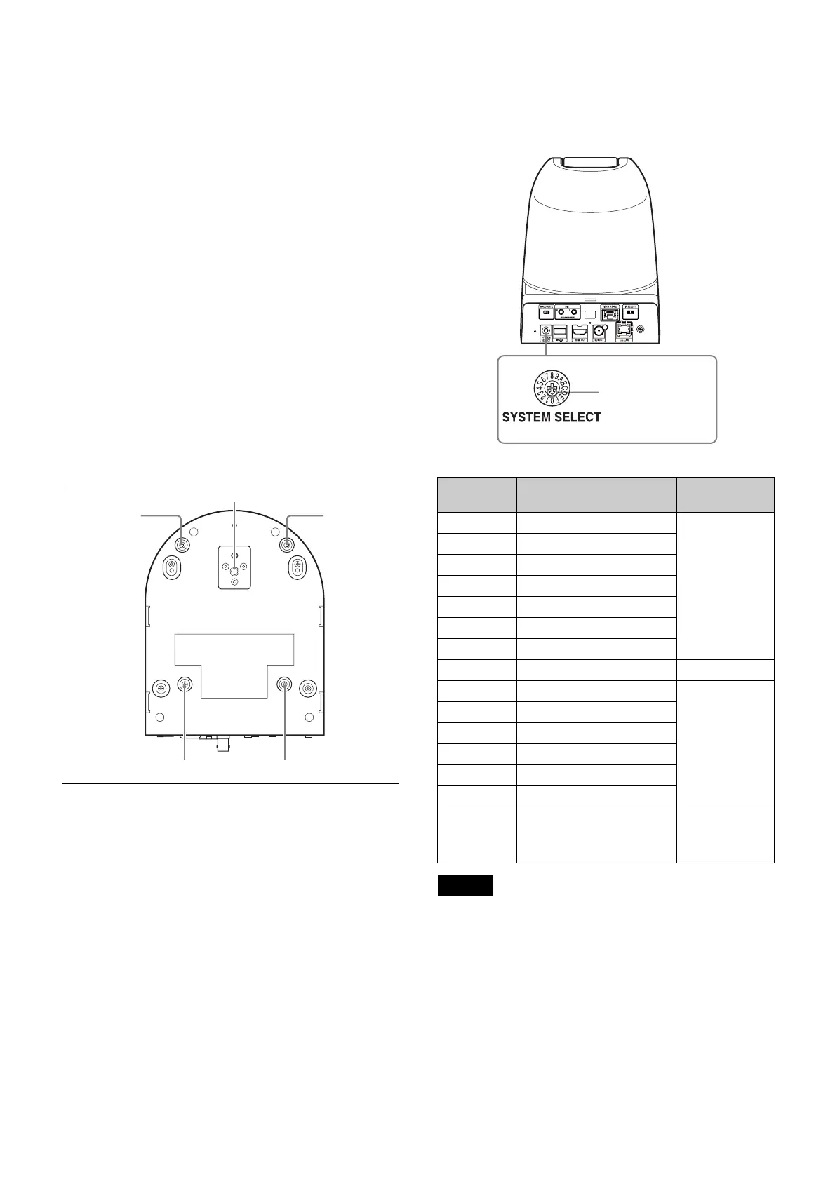
Bottom
r Tripod screw hole
Screw hole to mount tripod.
For details, refer to “Attaching the Camera to a
Tripod” (page 16).
s Ceiling bracket mounting screw holes
Screw hole to mount the supplied ceiling bracket (A)
when you mount the camera on the ceiling.
For details, refer to “Installing the Camera” (page 16).
Setting of the SYSTEM SELECT switch
This switch allows you to select the video format of the
signal to be output from the HDMI OUT/SDI OUT
connectors.
• Configure the setting of the switch before turning the
camera on.
Turn on the power supply after setting the switch.
• Always use a cross slot screwdriver to toggle the
switch. Otherwise, the cross chase might be stripped.
• When the switch is positioned as 7 (WEB UI), the video
format can be set via the external connection.
For details, refer to “Installation Tab” on page 52.
ql
qk
ql
ql ql
Switch
position
Video format
0 1920×1080p/59.94 (A)
59.94 Hz
system
1 1920×1080p/59.94 (B)
2 1920×1080p/29.97
3 1920×1080i/59.94
4 1280×720p/59.94
5 1280×720p/29.97
6 1920×1080p/59.94 (A)
7 WEB UI –
8 1920×1080p/50 (A)
50 Hz system
9 1920×1080p/50 (B)
A 1920×1080p/25
B 1920×1080i/50
C 1280×720p/50
D 1280×720p/25
E 1920×1080p/59.94 (A) 59.94 Hz
system
F No output –
Notes
SRG-360SHE
Set this arrow to the
desired video format.
 Loading...