The CONTROL AIII Control System was
designed to simplify the operation of audio
systems composed of separat_ Son?:
components. CONTROL A lII connections
provide a path for the transmission of control
signals which enable automatic operation and
control features usually associated with
integrated systems.
Cnrrently, CONTROL AIII connections
between a Sony CD player, amplifier (receiver),
MD deck and cassette deck provide automatic
function selection.
Note
Do not operate a 2 way remote control mitt when the
CONTROL AIII jacks are comlected via a PC
interface kit to a personal computer running "MD
Editor" or similar application Also, do not operate the
connected conlponent in a nlallner contrary to tile
fimcfions of the alJplication, as this may cause the
application to operate inconectly.
CONTROL AIII and CONTROL At
compatibility
Tile CONTROL A1 control system has been updated
to the CONTROL A 1II which is the standard system
in tlle Sony 300 disc CD changer and other recent Sony
components. Components with CONTROL A1 jacks
are compatible with components with CONTROL
AIII, and can be connected to each other. Basically,
the majority of the fimctions available with tile
CONTROL A1 control system will be available with
the CONTROL AIII control system.
However, when making connections between
components with CONTROL AI jacks and
components with CONTROL A 1II jacks, the
nmnber of fimctions that can be controlled may be
limited depending on tile component. For detailed
infomlation, refer to the operating instructions
supplied with the component(s)
If you have a Sony CD changer with a
COMMAND MODE selector
Ifyonr CD changer's (OMMAND MODE
selector can be set to CD 1, CD 2, or CD 3, be
sure to set the command mode to "CD 1" and
connect the changer to the CD jacks on the
amplifier (receiver).
Ill however, you have a Sony (D changer with
VIDEO OUT jacks, set the command mode to
"CD 2" and connect the changer to the VIDEO
2 jacks on the amplifier (receiver).
Connections
You can comlect np to 10 CONTROL AIII
compatible components in an?: order. However,
you can connect only one of each type of
component (i.e., 1 CD player, 1 MD deck, 1 tape
deck and I receiver).
(You may be able to comlect more than one CD
player or MD deck, depending on the model.
Refer to the operating instructions supplied with
the respectiYe component lbr details.)
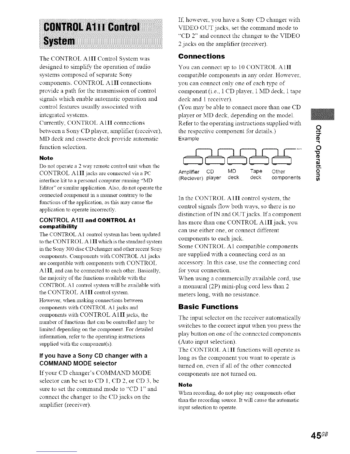
ExampIe
Amplifier CD MD Tape Other
(Reciever) player deck deck components
In the CONTROL AIII control system, the
control signals flow both ways, so there is no
distinction of IN and OUT jacks. If a component
has more than one CONTROL A 111jack, you
can use either one, or connect different
components to each jack.
Some CONTROL AI compatible components
are snpplied with a connecting cord as an
accesso1% In this case, use the connecting cord
lbr your connection.
When using a commercially available cord, use
a monanral (2P) mini-plug cord less than 2
meters long, with no resistance.
Basic Functions
The input selector on the receiver automatically
switches to the correct input when you press the
play button on one of the connected components
(Auto input selection).
The CONTROL AIII functions will operate as
long as the component you want to operate is
tnrned on, even if all of the other connected
components are not tnrned on.
Note
When recording, do not play any components other
than the recording somce. It will cause the automatic
input selection to operate.
o
O
"O
8'
45 GB
 Loading...