IM-S51-07 CTLS Issue 1
12
SP7-10, SP7-11, SP7-12 and SP7-20, SP7-21, SP7-22 Parameterization
3.1 General information
Most parameters for the positioner can be set locally, meaning that configuration only needs to be performed via the local communication
interface (LCI) or HART modem and PC in exceptional cases. You may also deny or restrict local modification and saving of parameters
by completely or partially blocking access to the configuration level (see Chapter "Inhibiting operation" on page 8 and the description
of the Function parameter on page 30). To simplify the process, the different parameters are grouped as follows:
ID Designator ID Designator Name
P1._ STANDARD Standard
P2._ SETPOINT Setpoint
P3._ ACTUATOR Actuator
P4._ MESSAGES Events
P5._ ALARMS Alarms
P6._ MAN_ADJ Manual adjustment
P7. _ CTRL_PAR Control parameters
P8._ ANLG_OUT Analog output
P9._ DIG_OUT Digital output
P10._ DIG_IN Digital input
P11._ FS / IP Factory setting, I/P type
The following sections provide an overview (in tabular and graphical format) of the overall structure of the parameter groups and
parameters.
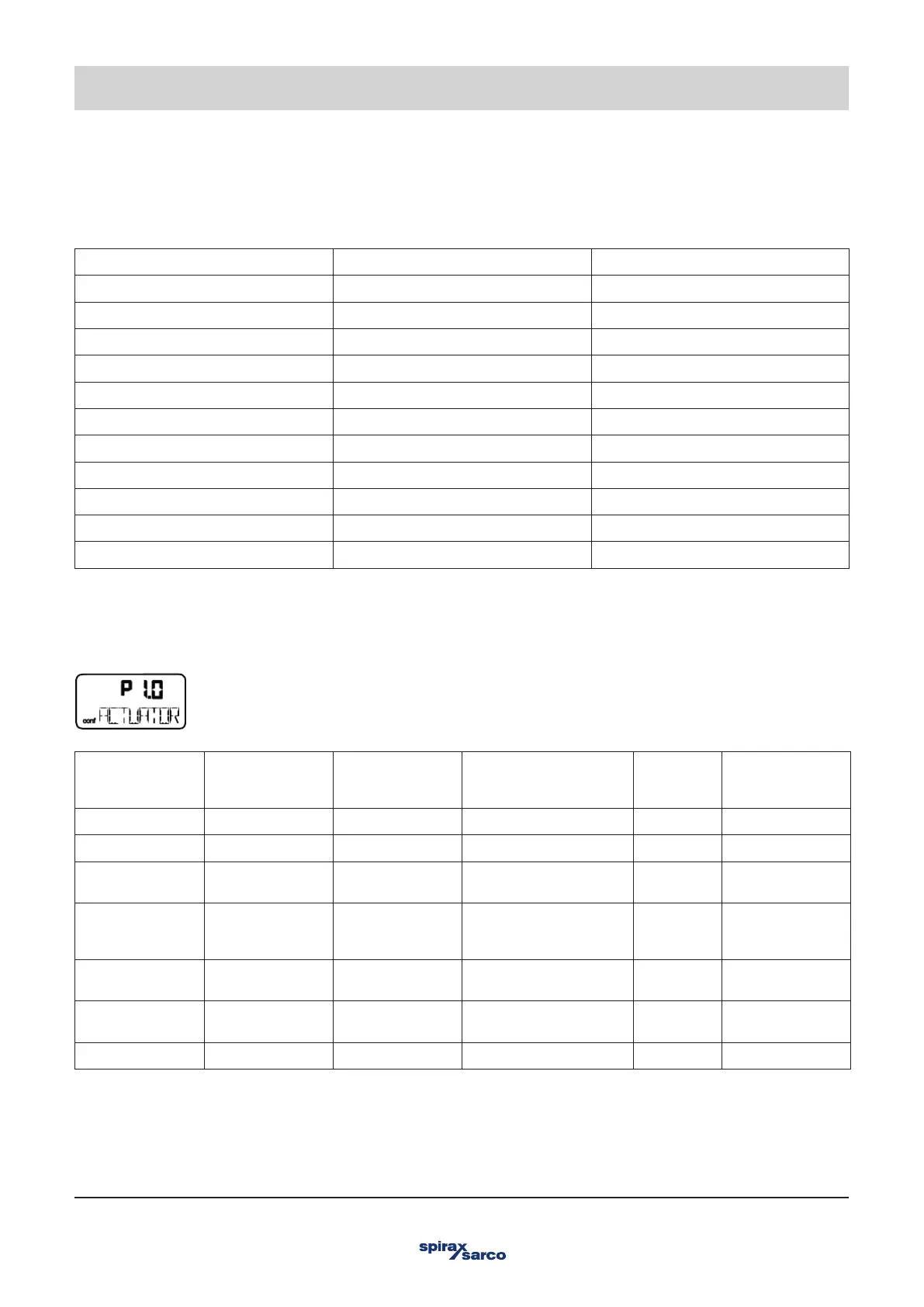
3.2 Example
3. Configuration
Parameter
(1st line in
display)
Indicator
(2nd line in
display)
Function Possible parameter
settings
Unit Factory Setting
P1 - STANDARD
P1.0 ACTUATOR Actuator type LINEAR, ROTARY - LINEAR
P11 AUTO_ADJ Autoadjust Command/Function is
being run
- -
P1.2 ADJ_MODE Automatic
adjustment mode
FULL, STROKE, CTRL,
PAR, ZERO_POS,
LOCKED
- FULL
P1.3 TEST Test Command/Function is
being run
- INACTIV
P1.4 EXIT Return to
operating level
Command/Function is
being run
- NV_SAVE
P2. SETPOINT