7
IM-S51-07 CTLS Issue 1
SP7-10, SP7-11, SP7-12 and SP7-20, SP7-21, SP7-22 Parameterization
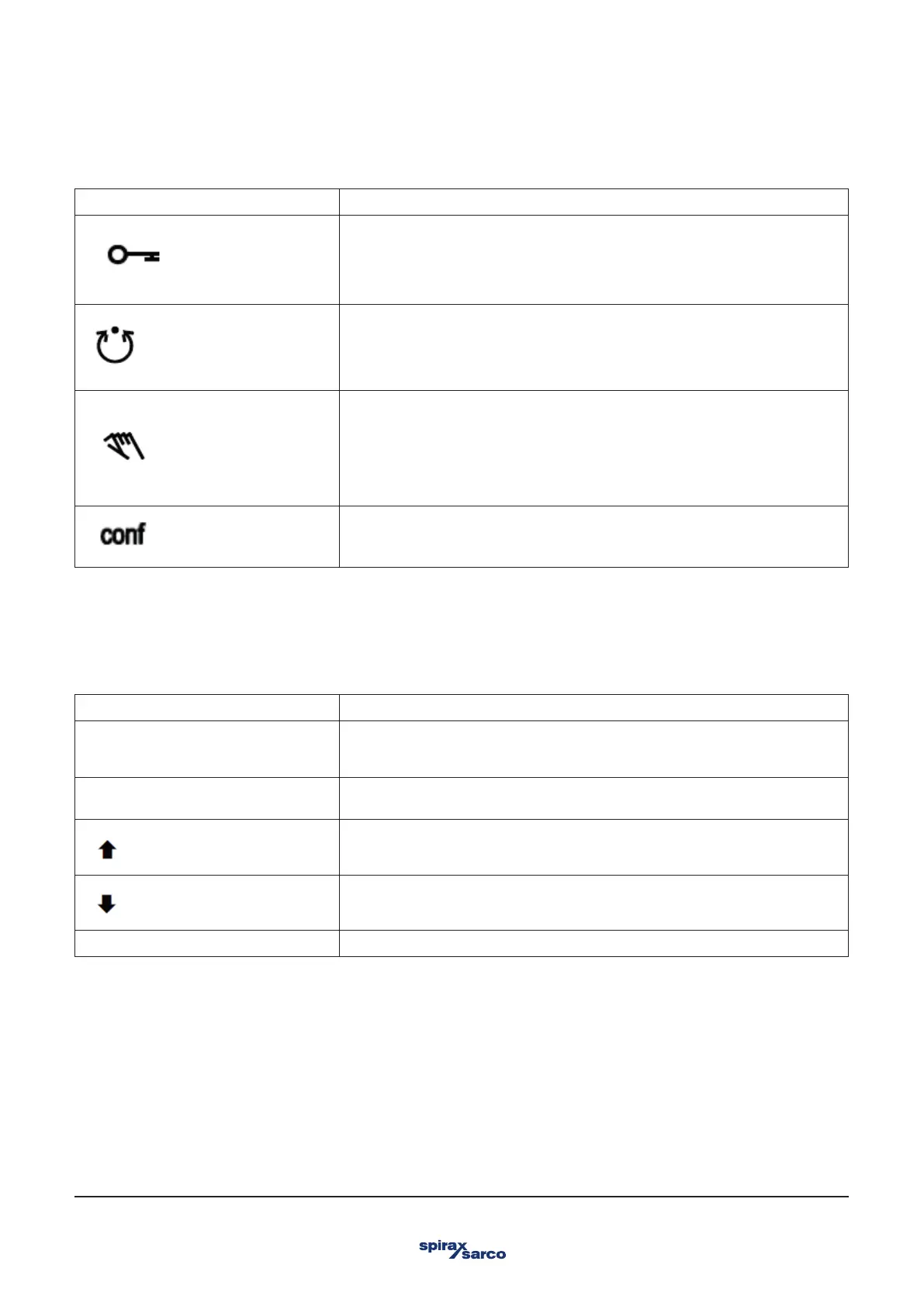
2.3 Description of symbols
Symbol Description
Operation or access is restricted.
Control loop is active.
The symbol is displayed when the positioner is in operating mode 1.0 CTRL_ADP
(adaptive control) or 1.1 CTRL_FIX (fixed control) at operating level. On the
configuration level there are test functions for which the controller will be active as
well. The control loop symbol will also be displayed when these functions are active.
Manual adjustment.
The symbol is displayed when the positioner is in operating mode 1.2 MANUAL (manual
adjustment within the stroke range) or 1.3 MAN_SENS (manual adjustment within the
measuring range) at operating level. At configuration level, manual adjustment is active
when setting the valve range limits (parameter group 6 MIN_VR (min. of valve range)
and 6 MAX_VR (max. of valve range)). The symbol will also be displayed when these
parameters are being set.
The configuration icon indicates that the positioner is at
the configuration level. The control operation is inactive.
The four operating buttons ENTER, MODE, ARROW UP and ARROW DOWN are pressed individually or in certain combinations
according to the function desired.
2.4 Operating button functions
Control button Meaning
ENTER 'E'
-Acknowledge message
-Start an action
-Save in the non-volatile memory
MODE 'M'
-Choose an operating mode (Operating level)
-Select parameter group (Configuration level)
UP direction arrow
DOWN direction arrow
Press and hold all buttons for 5 seconds Reset